 |
|

| |
|
|
|
|
|
|
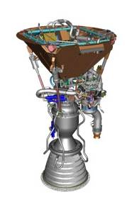
Rocket Propulsion System EOSystems' rocket propulsion system design is based on the specifications of the Falcon 1e launch vehicle. Falcon 1e is a launch vehicle under development by SpaceX Corporation and will be ready for all flights that will be launched in 2009 and beyond. After spending several hours studying different rocket systems, we chose this vehicle primarily for its cost of purchase and the fact that it meets our system requirement in almost the same way as some of the other more expensive rocket systems would. In this section, we will go over the specifications of the Falcon 1e rocket system and explain some of the basic concepts of rocket propulsion along the way. A key factor in choosing the Falcon 1e rocket has to do with its launch availability. SpaceX specifies that the Falcon 1e can be launched on short notice and at any time during the year1. Also, SpaceX Corporation provides several launch site locations on various parts of Earth which gives us flexibility for inserting the rocket into various inclinations. The launch sites include: Reagan Test Site in Omelek Island located 2,500 miles southwest of Hawaii (9°2.890'N, 167°44.585'E), SLC 3W Site in Vandenberg Air Force Base located along the Pacific Coast about 100 miles from Los Angeles, and a launch facility in Cape Canaveral Air Force Station (currently in the planning stages)1. EOSystems engineers have decided to launch our rocket from the Reagan Test Site due to the Island’s close proximity to the equator based on our orbital mechanics analysis. Liquid Combustion Rocket Chemical combustion rockets can be divided into two groups of propellant: solids and liquids. Many spacecraft launches employ both a solid rocket booster and a liquid propelled rocket. The Falcon 1e launch vehicle employs the Merlin 1C rocket engine, shown below, which uses liquid oxygen (LOX) and rocket grade kerosene (RP-1)4. Although it is more difficult to implement, a liquid rocket’s advantage is that it can be shutdown once ignited. As such, during launch operation the rocket is held back after ignition for a few seconds to perform engine analysis before liftoff. If any abnormal conditions are found, an abort process is initiated, and ignition of the engine is halted to prevent a failure during flight. This is extremely important to averting destruction of the expensive payload during launch/flight.
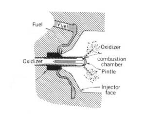
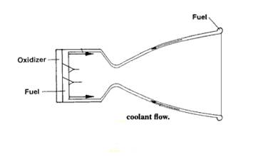
In a combustion process, fuel and an oxidant react to produce heat. During the process, the mass of each element remains the same. Reaction between oxygen and kerosene in the combustion chamber of the Merlin engine can be modeled as: C12H26 + 12.5O2 --> 12CO + 13H2O The reaction yields gases at very high temperature and pressure. Rocket Motor Design The Falcon 1e rocket motor design consists of an injector, a combustion chamber, and a nozzle. The motor uses a pintle injector which provides combustion stability. The injector allows fuel and oxidizer to enter the engine and mix. A central pin, a pintle, is used to spread out the oxidizer evenly (see figure below). This injector model is used for both stage 1 and stage 2. The first use of this technology was in the Apollo Moon program for the lunar module landing engine. As it was a success then, we are comfortable that a complete analysis can be performed, and we can implement it in our system4.
The injector introduces the fuels and oxidizers into a combustion chamber where they react to generate gases at very high pressure and temperature. However, the velocities of the gases are very low.
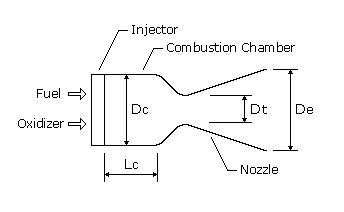
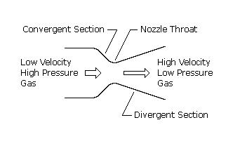
Finally, the gases enter the nozzle where they are converted into kinetic energy from chemical-thermal energy. The nozzle’s main task is to increase the velocity and, simultaneously, lower the pressure and temperature. This is achieved by expanding the gases in the divergent section of the nozzle. As a result very high thrust is produced (thrust = mass x velocity). The figure below provides a closer look into the nozzle’s design.
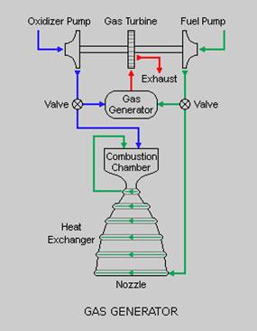
Engine Power Cycle Rather than use the more complex staged combustion cycle, the Merlin 1C engine uses a gas generator cycle, which is a simplified turbo pump design shown below4.
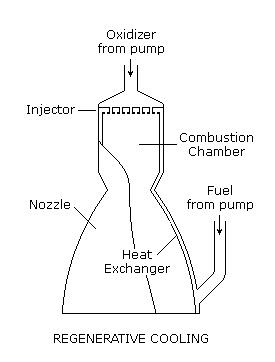
The gas generator cycle feeds a burner by mixing a small amount of fuel and oxidizer from the main flow, a process referred to as open cycle. As seen above, the generator sends hot gases through a turbine to generate power. This power is used by both the oxidizer pump and the fuel pump to send the propellants to the combustion chamber and then downstream into the main nozzle. The speed of the turbine can be increased by increasing the flow of propellants into the gas generator which in turn increases the flow into the main combustion chamber, creating a higher thrust2. Engine Cooling Efficiency of a rocket engine can be increased by cooling the nozzle and the combustion chamber. As the engine generates power, it also generates wasted heat energy. To utilize this heat energy, the Merlin 1C engine uses a regenerative cooling process5. In regenerative cooling, the hot gas liner is convectively cooled by flowing high-velocity coolant on the back side of the chamber’s wall containing the hot gas shown below.2,7
The coolant absorbs the heat and is then discharged into the injector to be used as a propellant2. While en route to the injector, the fuel collects thermal energy and returns it to the combustion process upon entry to the chamber; hence, the process gets its regenerative name7. This helps to increase the system’s efficiency. Regenerative cooling utilizes propellants in an efficient manner compared to ablative cooling (used in Merlin 1A and Merlin 1B engine designs6), where the combustion chamber side wall is melted, vaporized, and chemically changed to dissipate heat2. Ablative cooling process was not used in the design of Merlin 1C engine because of its high cost of development6. Cooling the engine is also extremely important to prevent it from cooking in its own heat. Another important factor in choosing the Falcon 1e is its thrust characteristic. Newton’s famous third law of motion states: for every action, there is an equal and opposite reaction. Every rocket system design is based on this elementary phenomenon. Chemical reactions of propellants combined in a combustion chamber form hot gases that are ejected at incredibly high velocity through a nozzle, providing the necessary thrust that propels a rocket.
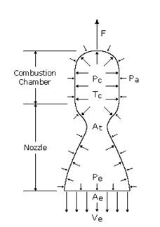
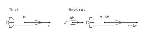
In rocket design, the basic thrust equations are: F = qVe + (Pe – Pa)Ae C = F/q = Ve + (Pe – Pa)Ae where F is the thrust, q is the rate at which the mass flow is ejected, Ve is the ejection speed of the exhaust gases, Pe is the pressure of the gases at the exit of the nozzle, Pa is the atmospheric pressure, Ae is the area of the nozzle’s exit, and C is the effective exhaust gas velocity2. The stage 1 thrust of the Falcon 1e rocket is 115k lbf (vac) and the stage 2 thrust is 7k lbf (vac)1. Specific impulse is the ratio of the thrust to the flow rate of the weight ejected. This can be explained with the help of the figure below.
At time t the rocket has a total mass M and is moving with a velocity v. After time t + ∆t, a mass ∆M has been ejected by the rocket as fuel is consumed. The rocket’s mass gets reduced to M - ∆M and its velocity increase to v + ∆v. The impulse response Isp is: Isp = F/(q x g) Where F is the thrust, q is the mass flow rate, and g is the gravitational acceleration at ground level. The units of Isp are seconds. Higher values of Isp mean lower propellant consumption for a given amount of momentum. Isp values are measured both at sea level as well as under vacuum conditions. The specific impulse values for the Falcon 1e rocket are4: Isp (sea level) = 255s (2.6kN.s/kg) Isp (vacuum) = 304s (3.0 kN.s/kg) In spite of the cost of the Falcon 1e rocket, the performance is comparable to other expensive rocket systems, such as the RD-170 [Isp (vacuum) = 338s] used by the Russians8, and the RS -27A [Isp (vacuum) = 338s] used in Delta II and III rocket systems9. One of the primary causes of failures in launch vehicles is the separation process1. This fact was kept in mind when choosing the Falcon propulsion system. The engines are in serial formation allowing only one engine to be used per stage. Therefore, the separation events have been minimized by reducing the number of stages to two. This increases the safety of the flight. The Falcon 1e provides a Reaction Controlled System (RCS) for collision avoidance maneuvers as well as altitude control and steering. A small amount of thrust can be provided in any direction desired. The thrusters are tilted forward by 20° and positioned in such a way to minimize any potential gas impingement on the spacecraft1. Each RCS has two tanks: one containing fuel and another containing the oxidizer. These propellants are expelled using pressurized helium to the RCS thrusters on demand10. RCS is also used to provide the required thrust to spin the spacecraft about its longitudinal axis. This helps in controlling the orientation of the spacecraft, especially at payload separation. Falcon 1e can provide rotation of the payload to about six revolutions per minute (RPM) at separation1. Rotation is also crucial for maintaining a uniform temperature throughout the spacecraft during its transit. A major reason for choosing the Falcon 1e is the standard services provided by SpaceX Corporation to their customers. A few key services relating to propulsion system are mentioned below1:
[1] http://www.spacex.com/Falcon%201%20Payload%20Users%20Guide.pdf |
||||||||||||||||||||||||||||||||||