|
Link Budget |
|
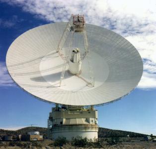
Earth Station NASA’s DSN is comprised of three earth stations roughly 120 degrees apart around the world at Goldstone, California; Madrid, Spain; and Canberra, Australia. Being placed 120 degrees apart allows constant observation of spacecraft while the earth rotates. At each earth station there is a 70 meter diameter antenna with the capability of using the Ka-Band (26.5 GHz – 40 GHz) for uplink and downlink satellite communication [1].
Fig. 1. Front view of the 70 m antenna at Goldstone, California.
Operation in Ka-band is preferable because path loss decreases as frequency increases. Space-based lasers λo ~850 nm — 980nm with (infrared) have been proposed, but present a large reception problem after propagating through atmosphere where they exhibit severe fading effects due to water absorption[2]. Table 1 encapsulates the specifications of the NASA DSN antennas for the Ka-band.
Table 1. NASA DSN Antenna Parameters
The gain of the DSN receiver antenna in dB was calculated using the standard antenna gain equation:
G = 10 log(4πArη/λ2)
In this equation, Ar : physical aperture area λ : wavelength in meters at the frequency of operation η : aperture efficiency.
With a 35 meter radius antenna and an estimated aperture efficiency of 0.7, the DSN antenna gain is 85.87 dB. The power transmitted can now range from 16 watts to 400 kilowatts at the NASA DSN due to a recent upgrade [1]. We will choose 400 kilowatts due to the enormous transmission distances of his effort.
Ka-band standards specify 34200 – 34700 MHz for transmit and 31800 – 32300 MHz for receive. We thus choose our uplink carrier frequency to be 34450 MHz and downlink carrier frequency to be 32050 MHz. Assuming , c = 3x10⁸ m/s the wavelength for uplinks is 8.17x10⁻³ m, and the wavelength for downlinks is 9.36x10⁻³ m.
Fig. 2. 4 x 6 meter SRS inflatable membrane reflector.
NASA has begun creating an inflatable/self-rigidizable antenna dish with an area of 4 x 6 meters made of thin polymer films that form a reflector surface and a canopy [4] and an estimated aperture efficiency of 0.7. This is ideal for a space probe application with limited weight and size requirements. Using the gain equation previously specified we calculate a theoretical gain of this antenna at Ka-band frequencies to be 63.82 dB. For the purposes of this proposal, we assume the same RF hardware is available for use in the probe as is in the DSN, providing high transmit power. Table 2 contains the specifications of the satellite antenna.
Table 2. Satellite Antenna Parameters
If we assume transmission directly from Epsilon Eridani using the above link parameters, the following downlink budget results:
Downlink Budget (Probe to DSN) The equation for a communications link budget in dB is Pr = Pt + Gt + Gr - Lp where Pr : Power received Pt : Power Transmitted Gt : Gain of transmit antenna Gr : Gain of receive antenna Lp : Path loss
Path Loss (LP) = 402.50 dB The path loss in dB is calculated using 20log(4πR/λ) where R : Distance between Earth station and satellite in meters λ : Wavelength in meters at the frequency of operation
The solar system is 10.5 light-years away resulting in a distance of 99,335,548,300,000,000 meters or 99.335 petameters. The path loss is calculated to be -402.50 dB.
Power received Adding all the components of the link budget results in a received power of -196.79 dB.
Pr = Pt + Gt + Gr - Lp = 56.02 + 85.87 + 63.82 - 402.50 = -196.79 dB Uplink Budget (DSN to Probe) The link budget for the uplink is the same equation as before for the downlink except now the transmit antenna is the receive antenna and vice-versa. The only change is that the frequency of operation is now 34450 MHz. The results of the link budget is a power received of -196.13 dB.
Pr = Pt + Gt + Gr - Lp = 56.02 + 86.50 + 64.45 - 403.13 = -196.13 dB
Shannon Capacity The Shannon ultimate capacity of communication (in b/s) is Blog2(1+CNR). If we assume the noise temperature of the transmit antenna is 20 K [and that we can limit the bandwidth of transmission to 100 Hz, then the CNR can be calculated to be -1.2 dB.
Table 3. Total noise power parameters and calculation.
CNR = 2.09x10⁻²⁰ W / 2.176x10⁻²⁰ W = 0.758 = -1.2 dB. The Shannon capacity of this link is therefore 81.4 b/s. That is 28.6 hours per image assuming no errors in transmission. However, BPSK or QPSK modulation with a CNR of -1.2 dB (Eb/No = -4.2 dB) would have a 50% error rate. This link is therefore largely untenable, as data recovery would be nearly impossible. Turbo coding, however, allows practical data transmission within a fraction of a dB of the Shannon limit, but does have its own limitations. |