Launch and Orbit System
Overview
The full 3SatImaging satellites constellation is capable of being launched on deployed from a single Soyuz-2 Launch Vehicle. This drastically reduces launch costs and the time required before the full constellation becomes operational. The final orbit of the satellites provides consistent coverage of the Earth with the best imaging conditions possible. To further explain the Launch and Orbit system this page is broken down into Launch, Deployment, and Earth Coverage sections.Launch and Orbit Characteristics
The 3SatImaging satellites will be launched into noon/midnight sun synchronous orbits. This type of orbit ensures one half of the the constellation is covering a range of longitudes at noon lighting conditions. Noon lighting means the most light from the sun will be available to the imager resulting in optimal imaging conditions and better images. Sun-synchronous also gives the advantage that the orbit will precess at the same rate as the Earth's orbit around the sun. This means the noon/midnight crossings will always occur for the duration of the mission lifetime, guaranteeing the best images for the duration of the mission. The rest of the orbit and constellation parameters for the satellites are shown in the table below.
| Launch Vehicle | Soyuz-2 |
| Altitude | 450km |
| Eccentricity | 0 |
| Inclination | 97.25° |
| Satellite Orbit Planes | 1 |
| Satellites Per Plane | 90 |
The best altitude for Earth sensing are the lower range of LEO since the targets are closer and thus the sensors have better resolution. For a 3U satellite, it is estimated using AGI Systems Tool Kit that the minimum altitude possible while maintaining a 10 year lifetime is approximately 450km. The eccentricity will ideally be zero since atmospheric drag will circularize any eccentric orbit in LEO. The inclination is chosen based on the equation below which describes the rate of orbital precession due to nonspherical Earth effects.
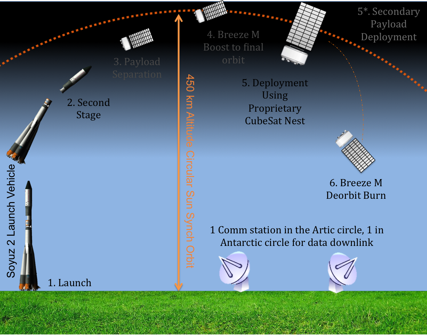
The obvious choice of launch vehicle for the mission is the Soyuz-2 due to its high payload to sun-synchronous orbits. The Soyuz-2 launches from the Baikonur cosmodrome and is capable of launching up to 4,500 kg to an 800km sun-synchronous orbit [2]. With this type of payload capability, it is possible to deploy all 90 satellites in a single launch using a simple CubeSat Deployer Nest concept. Each CubeSat weighs roughly 7.5 kilograms including deployer mass which gives a total required mass of just under 700kg. Due to the cargo capacity of the Soyuz, the launch has up to 3800kg remaining for other secondary ride along opportunities which will greatly offset launch costs for 3SatImaging. The graphic below shows the general concept of operations (CONOPS) for the 3SatImaging mission.
Deployment
The deployment of the satellites is based on a simple implusive phasing manuever that will be performed by each individual satellite. The Briz-M upper stage can only be restarted up to 8 times which limits its effectiveness in deploying a large number of satellites. Some kind of propulsive devices must be integrated on the CubeSats themselves. As mentioned above, the ideal phasing between the satellites is Δθ=4° and an overview of the deployment process is shown in the video below.
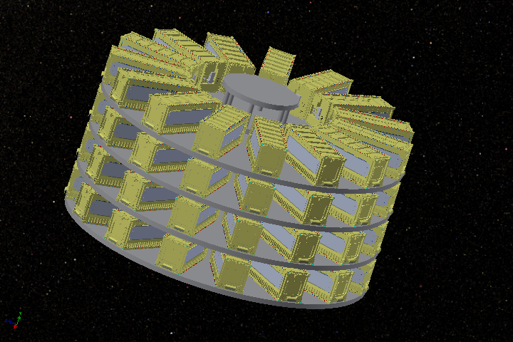
The deployer itself is based on a simple nested stack of CubeSat deployers designed to fit concisely into the Soyuz-2 rocket. The full stack of deployers is 32 inches tall and 60 inches in diameter, leaving space for another 30 ft and 3800 kg of additional payload. An image of a CAD model of the nest deployer is shown below.
The deployment phasing can be determined using a simple two impulse manuever based on two body dynamics. Phasing is based on the initial orbit period T and the phasing time Tphase. The equations below will walk you through how the phasing orbit is determined for 3SatImaging.
The phasing time is set to be the nominal orbit period divided by 90 for the number of satellites as follows,
This means that the phasing orbit must have a period of T+Tphase from which we can calculate the semi-major axis of the manuever.
At the point where the phasing manuever is started, we are either at apoapsis or periapsis of the resulting orbit. Since the initial orbit is circular, and we want to increase the period in the phasing orbit, the initial altitude when the maneuver is executed must be the periapse radius of the phasing orbit. Thus,
The eccentricity of this new orbit can then be determined by
At this point we have enough information to construct the two orbits since the inclination is unchanged in the phasing manuever and the rest of the Keplerian orbital elements, true anomaly, right ascension of the ascending node, and argument of periapsis can be set to zero without loss of generality. Using the Keplerian orbital elements conversion to cartesian state, the velocity at θ=0 can be computed for both the phasing orbit and the nominal orbit. The norm of the difference is the change in velocity ΔV required to change from the nominal orbit to the phasing orbit. Since you have to perform the manuever an additional time to get from the phasing orbit back to the nominal orbit, the total ΔV required is given as follows
The total velocity change required by the thrusters on each satellite is 55.7m/s, which is within the capabilities of the monopropellant thruster chosen for the mission.
Earth Coverage
The most crucial part of this section is the resulting Earth coverage from this constellation and orbit configuration. The video below shows how the constellation covers the Earth over time with the colormap representing zero coverage with blue and the maximum coverage with red. This orbit configuration attempts to continuously image new "slices" of the Earth with every orbit the full constellation complets by keeping all of satellites in one orbit plane. While this strategy gives the minimum number of satellites, it also contibutes to regions of overlap as consecutive satellites pass over portions of the same area. And due to the local radius at higher longitudes being much smaller than at the equator of the Earth, the regions above or below 80° or -80° lattitude can be imaged up to 10 unique times.
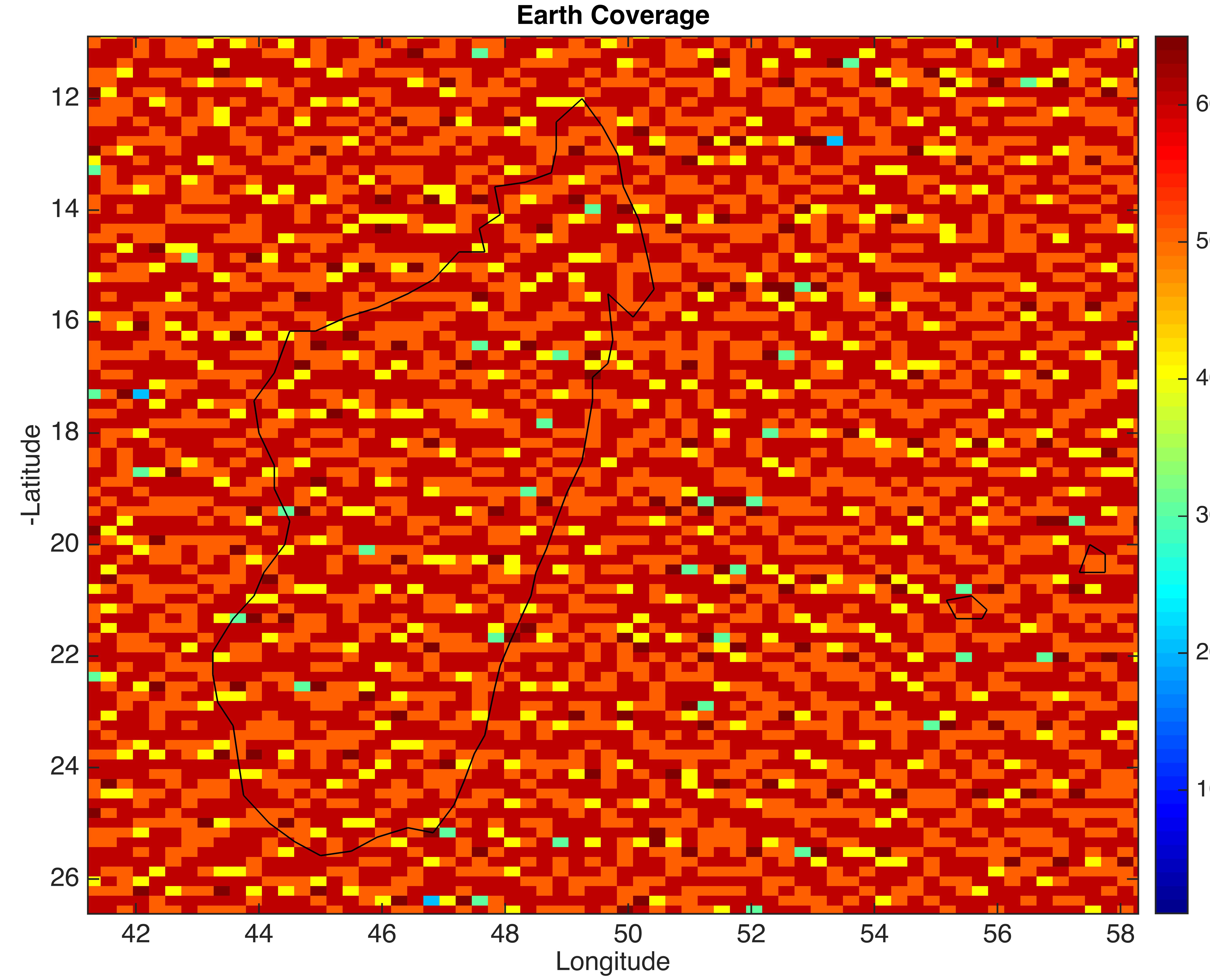
This coverage is analyzed by discretizing lattitude and longitude into bins smaller than the field of view of the imager. For 3SatImaging, these bins are 0.1748° Lattitude and 0.2622° Longitude. Then every satellite is propagated from its nominal inital position using a simple two body propagator. One second is used as the timestep and each satellite Cartesian position is converted to a satellite sub point on the Earth at that time step. Then for each satellite, the number of Lattitude and Longitude bins in the field of view is calculated and each bin gets a count. This is repeated for the duration of 24 hours to simulate the coverage of the satellite. Note:In the video below and the image following, the results show how the coverage would look if the satellites imaged throughout the full orbit. 3SatImaging will only be utilizing half of the orbit for imaging, but the result will be exactly half of what you see below.
The overlap in coverage can be seen in the image below. Such overlap is good since it presents opportunities to obtain a different image in a region if there was some kind of obstruction like clouds or other weather effects. However, this overlap is required as there are patches where the constellation only sees that area twice as can be seen in this image. Because of this, reducing the number of satellites by even just one would yield areas unobserved by the constellation even while other areas are observered 4 or more times.
One last aspect of the coverage you may notice is that the poles are never fully covered. Due to the choice of orbit, the satellites will never cross the true pole and thus will never truly be able to image the poles without tasking. While this region accounts for a minimal percentage of the Earth, and is a fairly uninhabited region, it is still possible for the 3SatImaging constellation to view the poles if required by a customer. Each satellite has active control and thus may slew to cover the poles if necessary. In general, only a true polar orbit is capable of capturing the poles regularly with no control but these orbits have disadvantages in that the precess over time. Eventually, this precession will give an orbit configuration where the satellites are near the terminator which would be the worst possible lighting conditions for Earth imaging. While these effects would be cyclical, sun-synchronous orbits avoid these altogether which is why they are being used for 3SatImaging.
[1] Bate, Roger R., et al. Fundamentals of astrodynamics: (dover books on physics). Dover publications, 2013
[2] Isakowitz, Steven J., Joseph P. Hopkins, and Joshua B. Hopkins. International reference guide to space launch systems. AIAA (American Institute of Aeronautics & Astronautics), 1999