|
|
|
Below is a time-lapsed animation of a computer solving Laplace's
equation using a simple relaxation technique. |
|
|
|
Cross-section of a
Symmetrical Microstrip Line |
|
![]() |
|
|
|
Notes: |
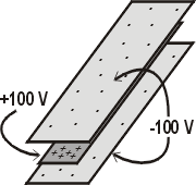
- Technical specifics about this example. The center strip is
held at +100V and the top and bottom strips are held at -100 V.
The boundary of the region is set to 0 V. The symmetrical
microstrip line (shown below) is used on multi-layer printed circuit boards to
transmit high-frequency signals with lower cross-talk and radiation
than regular microstrip lines.
|
 |
|
|
- Notice how the relaxation technique asymptotically converges to
the true value. The convergence slows as the number of
iterations increases.
|
- This particular cross-section is interesting because it shows two
separate "islands" of equipotential lines that grow and eventually
merge. For example, there are two rings of equipotential lines
for -80, -60, and -40 V -- one on the top plate and one on the bottom
plate. The -20 V equipotential line, however, is a single ring
around the entire cross-section.
|
- This style of microstrip line does a good job of confining its
fields to within its structure. There are very slight fringe
fields around the assembly.
|
- The final colored voltage map may look coarse and blocky, but the
relaxation technique is actually very accurate. We can use some
fancy rendering and interpolation between points to make a smoother
map. In fact, that is what the equipotential plots have done,
which is why they look so smooth.
|
|
|
