Channel Modeling for
Zhe Fan,
Student of Georgia Institute of Technology
I.
Introduction
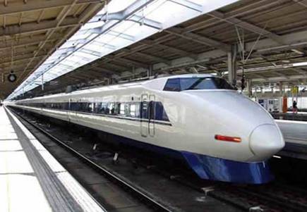
The Shinkansen provides an easier and
faster way of
transportation. It travels up to 260km per
hour; it is
the fastest road transportation device today.
However,
moving at such speed provides a harsh radio propagation
environment
for cellular phones. Because of the
scattering
mechanism
in mobile and portable radio communications,
the
received signal is usually
composed of the multiple
reflected
waves from different paths. The vector
addition
of
multiple signals can result in a distorted signal and may
cause
amplitude dropout at receiver known as multipath
fading [1]. When the
train is moving
at top speed, in
addition
to multipath fading, the situation
is further
complicated
because of the presence of small-scale fading
due
to multipath waves that all originate from the serving
base
station. The received signal power will
fluctuate severely due to the fading, and it is impossible to connect to a base
station while the train is moving at a high speed.
II.
Channel Modeling
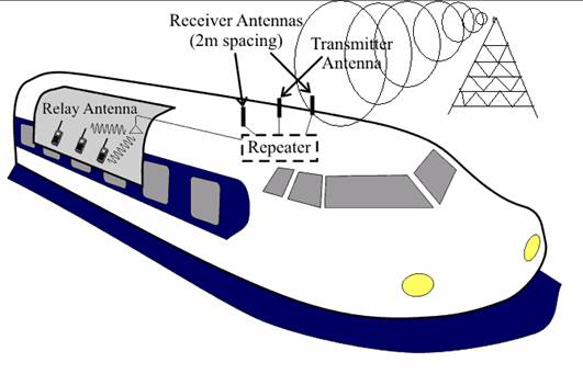
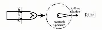
In order to solve this problem, transmitter and
receiver antennas are installed on the top of each lead car (Figure
1). This will maintain communication
with one or more base stations near the train, performing all of the high-speed
hand-offs during travel. The receive
antennas will maintain the communications with one or more base stations near
the train at all times, performing all of the high-speed hand-offs during travels. The transmit antenna will communicate with
the passengers’ cellular phones, relaying the data to the outdoor base
stations.
Figure 1. Receiver
and transmitter antenna on top of lead car.
To
be able to truly understand how this works, first we will model the multipath
channel with the appropriate set of received plane waves. The common frequency used for cell phone is
around 1.9 GHz. A good model of azimuth spectrum
in this band :
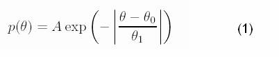
The constant A is average received power which will varies
on different power received from each base station, however it will not have
significant affect on the distribution or the statistics of fading. In the model we are studying, 10 is used for
A in the code. θ0 is the
azimuth direction of peak arrival. We
are only studying 0 and 90 degrees azimuth direction in the model for simplicity
purpose. The value θ1 is the
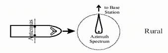
thickness of the distribution. When a
train is traveling in a rural area, the signal has less reflection, hence it
has a relatively small θ1; when the train
is traveling in an urban area, the signal has more reflection due to higher
density of objects around, and hence it has a relatively larger θ1. The θ1 is 3 degrees in rural area and θ1 is 120 degrees in urban area. Figure 2 describes all
the four cases of multipath wave interference.
Figure 2(a). Azimuth spectrum in rural
area at 90 degrees angle arrival. Figure 2(b). Azimuth spectrum in rural
area at 0 degree angle arrival.
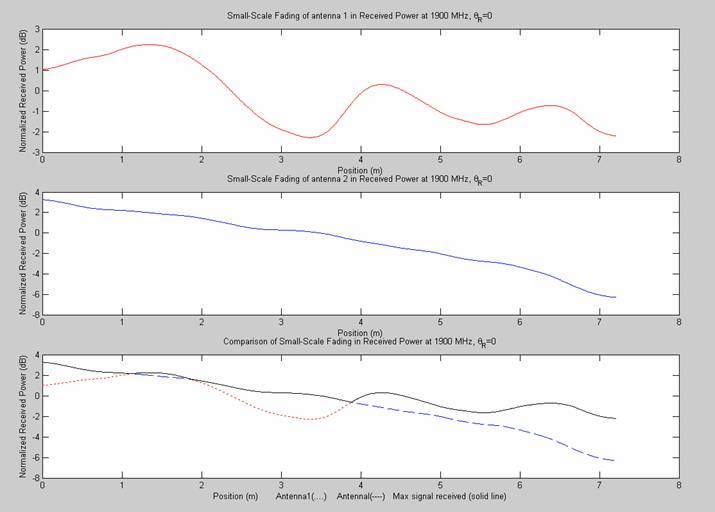
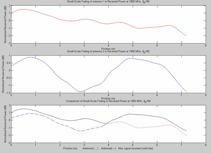
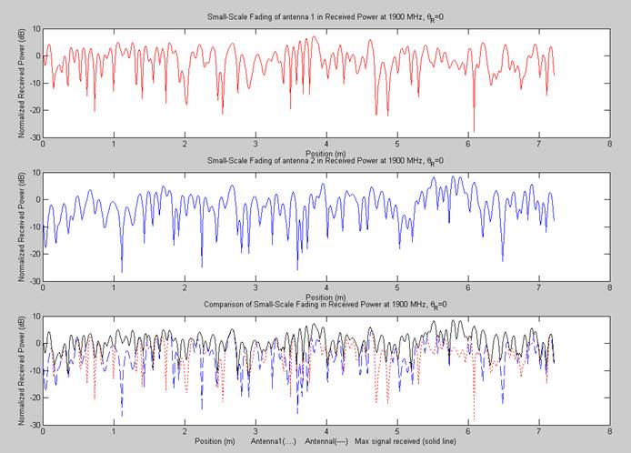
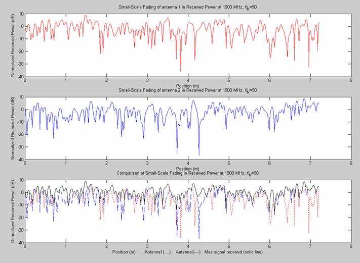
Plot 1 and plot
2 show the small-scale fading in rural area. The antenna received less interferences in
open area, the antennas only switched two, three times, the sampling rate for
rural are is relatively small. If we
look at plot 3 and plot 4, they are
the small-scale fading in urban area, the signal is transmitted in a more
complicated multipath channel due to reflection. The graph fluctuates severely, the antenna
switches much more frequently, the plot require much higher sampling rate.
III.
Conclusion
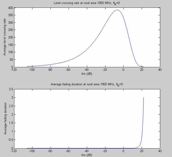
After running the simulation, we discovered that when
the train is traveling in urban area, the level-crossing rate is higher, and
the fading duration is lower (Plot of level-crossing rate and
fading duration for urban area).
This is indicating that in a multipath
channel, the signal fluctuates severely (Plot of the fading in
urban area), the fading is combination of multipath
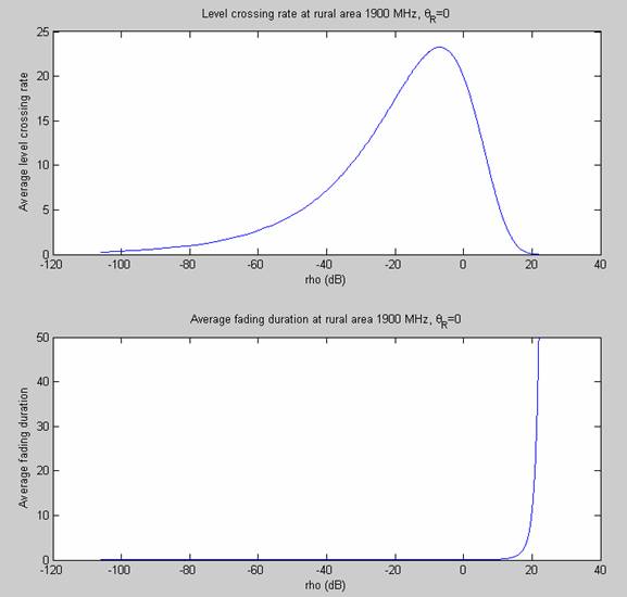
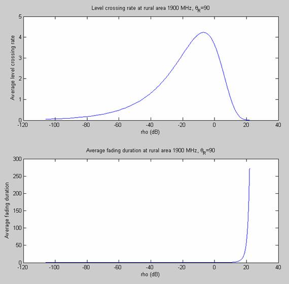
fading and small-scale fading. When the train
is traveling in rural area, the
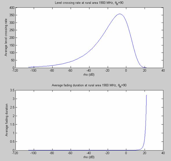
level-crossing rate is lower, and the fading duration is higher (Plot of level-crossing rate and fading duration for rural area). This is indicating that in an open area, the
signal fluctuates less severely (Plot of the fading in rural
are), the fading is mostly due to small-scale fading. The level-crossing rate at urban area is much
higher than the one at rural area, thus we can conclude that the frequency of
antenna switching in urban area is much higher than the one at rural area. The level-crossing rate at urban area has a
maximum of 375, according to this number, every level-crossing must have at
least two samples to acquire an accurate result, hence
the recommended sampling rate is approximately 750/s.
IV.
Appendix
3.
Plots
Plot
2. Fading in rural area with azimuth angle of 90 degrees
Plot
3. Fading in rural area with azimuth angle of 0
degree.
Plot
4. Fading in rural area with azimuth angle of 90
degree.
Plot
5. Level-crossing rate and average fading duration in rural area
with azimuth angle 90 degree.
Plot
6. Level-crossing rate and average fading duration in rural area
with azimuth angle 90 degrees.
Plot
7. Level-crossing rate and average fading duration in urban area
with azimuth angle 0 degree.
Plot
8. Level-crossing rate and average fading duration in urban area
with azimuth angle 90 degrees
V.
Reference
[1.] Wang, Li-Chung, Channel Modeling and Architecture for Cellular-Based Personal Communications. School of Electrical and
Computer Engineering, Georgia Institute
of Technology, 1996
[2.] Durgin, Gregory D.,
Space-Time Wireless Channels.
[3.] Durgin, Gregory D., Theory of Multipath
Shape Factor for small-scale fading Wireless Channels