|
TransmiTech
|
|
| Software Packages: | |
|
For the last 2 months, TransmiTech has developed the TX2000 software which is capable of estimating the radiated power propagated in different sectors around a base station transmitter antenna by simply knowing the terrain topology and some information related to the transmitter, such as: azimuth, location (coordinates), altitude, effective isotropic radiated power, and frequency of operation.
How does the TX-2000 software works? The TX-2000 model was built with the use of real measured data on four different sectors in country areas of the United States. Based on Path Loss theory and with the aid of measured data, the software is capable to estimate the path loss exponent of the region to be studied by the use of the following equation:
 [Eq. 1]
Once the path loss exponent “n”, as denoted in eq. 1, is calculated, we are ready to enter into the modeling section of our software. In order to make our model as precise as possible, we focused on following the well known theory of link budget. The link budget equation provides a useful relationship between path loss and both the power and gain of the transmitter and receiver antennas, as shown by:
[Eq. 2]
(Click here to see corresponding code)
where P is the received power, PR is the transmitted power, is the gain of the transmitter, is the gain of the receiver, and PL is the path loss defined as the ratio of the effective transmitted power to the received power, calibrating out system losses, amplifier gains, and antenna gains [1], as shown by:
[Eq. 3] Based on the theory previously described, our engineers decided to implement two key functions in order to complete the software. The first and most simple function was intended to compute the distance “r” from the base station transmitter to each point were power needs to be measured. As shown before in eq. 2, the distance “r” separating the two antennas is an important factor to be used in the prediction of the received power at a desired location. The function used to calculate the distance was based on the geometrical concept that allows computing the distance between two given point on a system of coordinate:
(Click on here to see corresponding code)
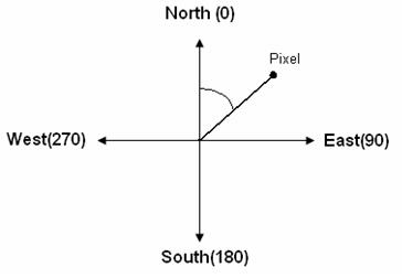
Any person with some level of knowledge in antenna
theory knows that base stations used in cellular communications have
some directionality in order to transmit power across a desired area. A
base station with a gain of
Figure 1. Implemented coordinate system.
The ang2 function is then used in the anglePower function which allows modeling the beam with pattern at which power is transmitted by the base station. Our model multiplies the power received inside the beam width area by a factor of 0.9 in order to slow down the decaying rate of power as waves travel away from the base station.
Our engineers detected by carefully studding measured data provided from testing antennas, that in some cases the power intensity at the vicinity of the antenna needed to be reduced and adjusted in order to produce a more realistic model. The advantage of the TX-3000 model is that it implements an additional function that is note used in the TX-2000 model. This new function is called distancePower, and was created by our designers in order to tunes the total power received depending on the separation between the transmitter and the receiver.
This software is still in progress and as an expansion of the TX-3000 it will be the most complete among the three that our company provides. The TX-4000 intends to account for diffraction effects based on knife edge theory. Knife edge effect is explained by Huygen's principle, which states that a well-defined obstruction to an electromagnetic wave acts as a secondary source, and creates a new waveform [2]. This new waveform propagates into the geometric shadow area of the obstacle, as shown in the following diagram:
Figure 2. Knife-Edge effect [2].
Up to now, our engineers are still studding and trying to understand the effects of diffraction and for the moment, our designers decided to reduce the power at locations where the differences in altitude with respect to the base station were larger than 70 m, as a simplistic way to account for diffraction. By clicking here you will be able to observe the code in progress.
|
|