4.0: Satellite to Earth Link
The link from the relay to Earth may be simple conceptually, but the vast distances involved proove to be a design challenge. As in all engineering tasks the challenge is to balance performance and cost.
The probe data has been merged into a 24kbps stream and must now be relayed to Earth. The primary problem of the link is the vast distance between Neptune and Earth. To overcome this distance a combination of brute force transmission power and complex data encoding will be utilized.
The second problem deals with the fact that for part of the operation the relay satellite will not have a direct line of sight for transmission to Earth. To negate this problem buffering will be implemented so that data can be transmitted outside of real time constraints. To extend on this solution all data will be buffered to ensure any unforseen problems in other subsystems will not destroy the possibility of sending the data.
4.2: Relay Communications
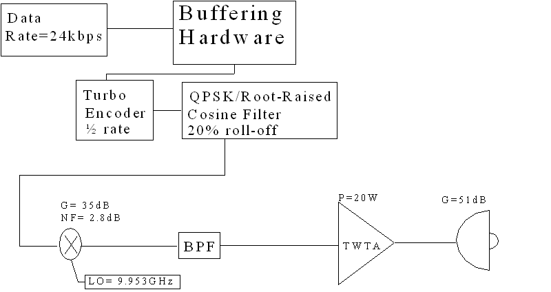
Buffering Hardware
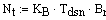
The buffering hardware needs to accommodate the worst case situation. If there is a hardware malfunction and transmission is delayed then all of the probe data may have to be buffered until the problem is resolved. To accommodate buffering there needs to be
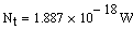
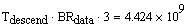 bits of storage. This correlates to
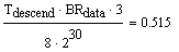 Gigabytes of data. This amount of data storage can be achieved with solid state devices such as
flash memory
from
Maxwell Technologies
.
Gigabytes of data. This amount of data storage can be achieved with solid state devices such as
flash memory
from
Maxwell Technologies
.
The control system will have to determine if there is occlusion between Neptune and Earth and keep track of what data has been sent. With this method the data can be transmitted real-time as data is received. When the boresight is interrupted the data is stored and held for transmission when the link is re-established.
Turbo Encoder, Rate=1/2
Data sheet:
AVTEC Systems
The 1/2 rate turbo encoder will take the 24kbps stream of data and encode it into a 48kbps stream. This process will allow the signal at Earth to be recovered nearly perfectly with a SNR of 2dB
3
or above.
BPSK/Root Raised Cosine Filter
Data sheet:
Comblock COM-1002
Data sheet:
Comblock COM-2001
Data sheet:
Epson EG-2121CA PECL
The same equipment from the probe design will be used to transform the digital data into a QPSK analog signal with a root raised cosine pulse. With QPSK signaling the baseband bandwidth will be halved, compensating for the turbo coder's data rate doubling. The bandwidth analysis follows:
pulse freq:
roll-off factor:
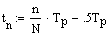
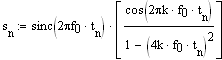
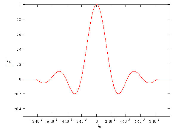
Setup the four bit period pulse and its FFT:
The final pulse:
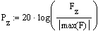
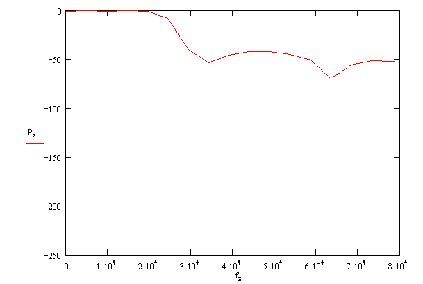
The fft and its power spectrum:
The pulse in the time domain:
The power spectrum:
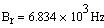
The first null below 50 dB down occurs at 3.417kHz. The bandwidth for the probe signal after mixing will be 6.834kHz
Upconverter, 9.953GHz Oscillator, and Bandpass Filter
Data sheet:
Lucix Up/Down Converter
Data sheet:
Lucix 9.953 Dielectric Resonator Oscillator
Lucix can provide the up converter and the oscillator that will mix the signal up to the carrier frequency of 9.953GHz. The company
MFC
can provide filter centered at 9.953GHz.
High Power Traveling Wave Tube Amplifier
Data sheet:
Ar Worldwide
This 20W amplifier will provide the drive for our dish antenna. It has an operating range of 4.2-18GHz.
Dish Antenna
A dish antenna will be used to get the transmission to Earth. The dish will have to be electrically large to get the gain up high enough to span the vast distance. Dish alignment will be controlled by a 3 degree of freedom gimbal motor that is controlled by information provided by the navigation software. The control should be such that the dish is oriented with maximum directivity towards the earth. Maximum directivity occurs at the center of the dish along the vector normal to the directrix.
The dish calculations follow:
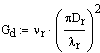
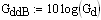
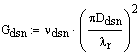
Calculation of Dish Gain:
Relay Characteristic Values
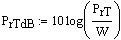
The power transmitted:
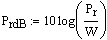
The power transmitted in dB:
The gain of the dish
Signal Bandwidth
4.3: Deep Space Network Reception
System Temperature
Aperture Efficiency
Dish Diameter
Dish Gain
4.4: Link Budget Analysis
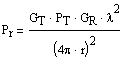
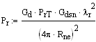
The furthest distance that Neptune and the Earth can ever be away from each other occurs when the earth is directly behind the Sun with respect to Neptune. This is not a frequently occurring event, but it will serve as the worst case scenario for the link budget calculation. The values used are from section 2.1.
Max distance from Neptune to Earth:
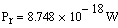
The power received at the Earth:
Next the system noise will be calculated
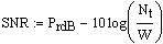
Equation for system noise (see
section 1
for constants):
The bandwidth of the transmitted BPSK signal:
The noise incorporated into the signal:
The SNR of 6.7dB is well above the 2db level that is required for nearly perfect reception of a turbo coded signal.
4.5: Transmission Control
The control system for the communications unit will have to have the navigation software alert it as to when Neptune is between the satellite and Earth. When occlusion occurs transmission will stop and data will continue to be recorded. When the navigation package declares the link clear the transmission can resume where it left off.
The relay will be allowed to transmit until its power system expires. This expiration time will be discussed in the power system section.
.