Crossed-Slot
Patch for Solar-Array Integration
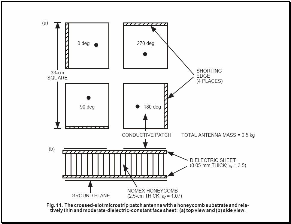
A crossed-slot patch [2] is a microstrip antenna element that consists of four
1/4-wavelength-long sub-patches, as shown in Fig. 11. Each sub-patch has a
square or slightly rectangular shape with one edge electrically shorted to the
common ground plane. This electrical shorting can be accomplished by connecting
the sub-patch and the ground plane either by a small, continuous, thin metallic
sheet or by many metallic shorting pins (8 to 10 per edge). The four
sub-patches are shorted at four sequentially located edges. The four
sub-patches also are excited at four sequentially located 50-ohm input
impedance points by four coaxial probes. These four feed probes then are
combined behind the ground plane by a hybrid circuit that provides the needed
0°, 90°, 180°, and 270° electrical phases. The four sub-patches are separated
from and supported above the ground plane by a one-inch-thick non conducting
honeycomb panel. Since a sub-patch radiates only from its three open edges,
foreign low-profile objects (metallic or nonmetallic) can be placed on top of
each sub-patch without significantly disturbing the radiation characteristics
of the antenna. Consequently, solar cells can be placed on top of the four
sub-patches of the crossed-slot patch antenna, as shown in Fig. 10. Although
all open edges of the four sub-patches radiate, the major portions of the
radiated fields originate at the central crossed slots. Since each slot
radiates with a cosinusoidal amplitude distribution
with the maximum field located at the slot center, the crossed-slot patch has a
very small effective radiating aperture, which leads to a relatively broad
far-field beam.
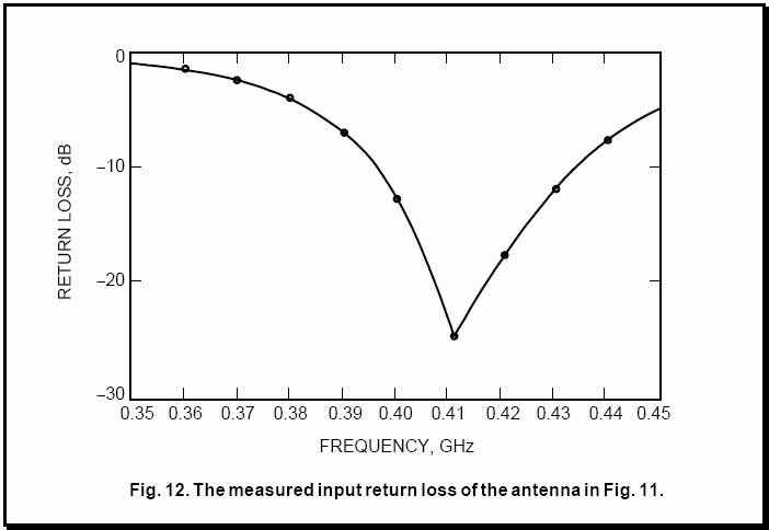
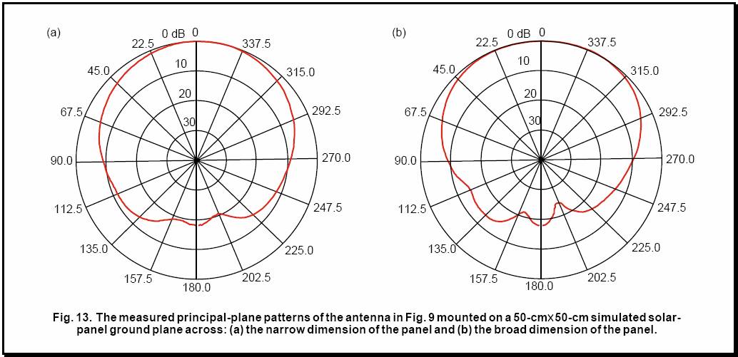
The antenna, measured at a representative frequency of
410 MHz, has a peak gain of 4.5 dB. From these patterns, it is clear that the
low-profile crossed-slot patch antenna does radiate a relatively broad beam and
is capable of integrating with the solar array [Full PDF].