Final project: The Martian Network
Mars Satellite <-> Mars Satellite Link Design
Each of the area stationary satellites in the equatorial orbit maintains a link to one of the remaining two area stationary satellites and one of the satellites in the polar orbit for routing purposes. Each satellite in the polar orbit, on the other hand, communicates with solely with one of the area stationary satellites. Note that no two polar orbit satellites communicate with the same satellite in the equatorial orbit.
A line-of-sight is always maintained on the link between two satellites in communication.
The block diagram of the receiver and the transmitter for these links is very similar to the ones described in the section Earth<->Satellite Link Design. The only difference lies in the fact that up to 100 signals will be transmitted simultaneously here: 50 signal from terminals on Mars and 50 signals from Earth. Hence, in the link budget calculation it has to be considered that there can be up 99 interferers degrading the quality of the desired signal..
The block diagram of the satellite transmitter on the satellite <-> satellite link.
The block diagram of the satellite receiver on the satellite <-> satellite link.
The spectrum around and on Mars has not been allocated yet (and is not likely to be in the near future), therefore signal bandwidth is not a problem there. The transmit power, on the other hand, is a very valuable resource to the satellite, since in the long run the satellites depends on the power from it solar cells. To save transmit power we increase the spreading factor to 256. Again, Gold codes are used for spreading.
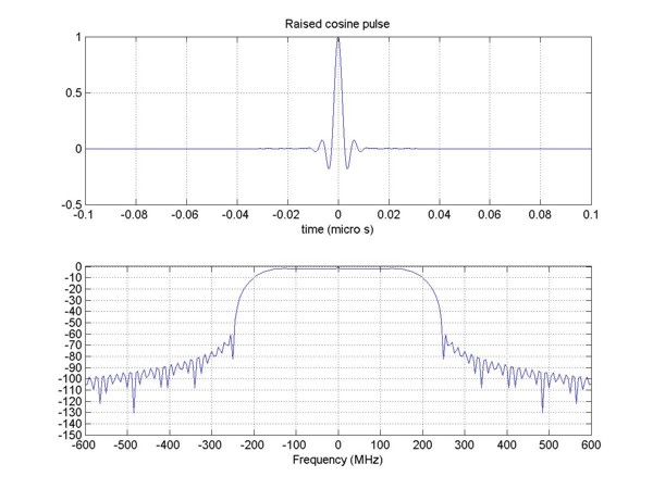
The signal is QPSK modulated and a turbo code with a rate 1/2 is used, same as in the Earth<->Satellite link. Due to the higher spreading factor, the symbol rate will be higher as well and therefore a new pulse needs to be designed. On this link the antenna will transmit the signal at 10 Watts, so the sidelobes at out-of-band frequencies do not have to surpressed as much as in the Earth<->Satellite link. We lower the roll-off factor to 0.3, but keep the high time (24* symbol period) to avoid polluting adjacent bands and to use effectively use the bandwidth. The figure below shows the new pulse in time and frequency domain. It can be seen that the bandwidth of signal will be 500 MHz.
If all satellites are at the same altitude, which is the case in our design, the maximum distance between arbitrary two can not be larger than two times the radius of the sphere that the satellites describe. Since the satellites are 20427 kilometers from the center of Mars, the maximum distance beween two satellites can not exceed 40854 kilometers. We will regard this distance as the worst case scenario in the link budget calculation.
The chosen frequency bands are 7.25-7.75 GHz and 8.00-8.50 GHz for links represented by yellow and green arrows, respectively. Both the receiver and the transmitter will use dish antennas with the radius of 2 meters and an efficiency of 0.9, which deliver a gain of 43.4648 dBi at 7.50 GHz GHz and 44.2927 dBi at 8.25 GHz. The physical temperateure as seen by the satellite was assumed to be 140 K and the device temperature of the low-noise amplifier 50 K.. With these components, the carrier-to-noise ratio at the receiver (see how C/N was calculated) will be 4.1248 dBi for the 7.50 GHz link and 4.1252 dBi for the 8.25 GHz link. Both values are well above the threshold for the target bit error rate.