 |
||||||||
|
||||||||
System Design |
||||||||
|
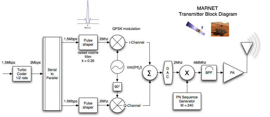
Since all of the transmitters and receivers will be using the same modulation scheme and structure, their topologies will be similar for each device. A basic layout of the transmit and receive topologies are presented in this section. For the transmitter, the basic architecture is shown in Figure 11. The signal is first encoded by the turbo coder, doubling the data rate. The serial to parallel converter spilt's the data streams into one that will become the I and Q channels. Each channel is pulse shaped, and then unconverted to the respective frequency of the transmitter. Depending on the frequency, the up conversion may have to be done at hardware instead of in digital as shown in Figure 11. The major difference in the modified structure would be the placement of the DAC. After the signal is up converted to RF, it is then chipped with the specific coding sequence for the ground terminal. The signal is then amplified and transmitted to the receiver. Figure 11: Basic Transmit Topology
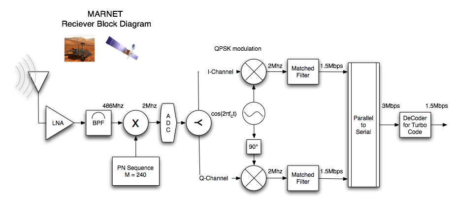
The receiver has a very similar structure to the transmitter. As shown in Figure 12, the LNA amplifies the signal while maintaining the SNR. The signal is when chipped with the coded sequence and filtered (not shown). The selection of a chipping sequence is crucial such that the signal correlates only with itself and no other signals, and it only correlates every once every chipping cycle. Once the signal is despread and sampled, the signal is down converted to to baseband and separated into I and Q channels. The signals are then detected through a matched filter that extracts the bits from the analog signal, and the it is decoded by the turbo coder. Figure 12: Basic Receiver Topology
|
||||||||