Magnetron Directional Amplifier
Although magnetrons are used in conventional microwave-oven products, they can also be used for the Space Solar Power application to produce microwave power. High DC power that will be harvested by the Photovoltaic cells from solar energy will serve as a DC input to the magnetron. The magnetron will do the DC to RF conversion; the generated microwave power will be fed to the satellite dish antenna through a waveguide or coaxial cable which will direct the power back to the earth stations rectenna.
In order to provide a better performance in terms of phase and amplitude tracking of the generated RF wave, a type of magnetron (enhanced conventional magnetron) for a satellite power system is used: the Magnetron Directional Amplifier (MDA).
The MDA is a conventional magnetron with the addition of a passive directional device (a ferrite circulator or a magic T), the output sensors and compensators for both amplitude and phase tracking, and the feedback control circuits. As shown in the DOE/NASA study, the magic-T passive directional device is preferable for Space application. The conventional magnetron used for the MDA is composed of pyrographite cooling fin, the buck-boost coil, the magnetron tuner with solenoid, and the samarium cobalt magnets.
Moreover, the MDA has a very high electrical efficiency as reported during the comprehensive DOE/NASA study of the satellite power system.
Some other benefits of the magnetron directional amplifier are listed below:
- Phase and amplitude tracking capability of magnetron directional amplifier
- Exceptionally high signal to noise ratio
- Long life based because of low operating temperature of the carburized thoriated tungsten cathode
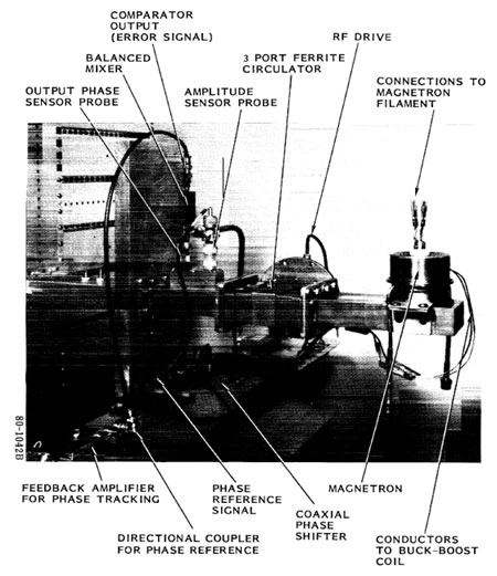
Figure M5. Overall View of Phase and Amplitude Control Circuits on Test Bed
The phase and amplitude tracking control circuit is shown in Figure M5. It was demonstrated that the phase and amplitude tracking control could be made accurately and simultaneously. Two actuators were used for both amplitude output and phase output control. The actuator used to control the amplitude output is a buck-boost coil which adds to or subtracts from the residual magnetic field produced by the permanent magnets. The actuator used to control the phase output is a motor driven mechanical phase shifter which compensates for the phase shift in the magnetron directional amplifier that is caused by various environmental and operational factors. The experimental equipment showed a capability in phase tracking to within + to -1degree and output amplitude tracking to within + and -30%. The experiment also showed that it was possible to get a 20db gain.
The phase and amplitude tracking require the need of auxiliary DC power. This auxiliary DC power can be obtained from rectifying a portion of the generated microwave power with Schottky barrier diodes made with GaAS material. The same concept used for the AC to DC conversion at the rectenna can be used here to produce the auxiliary power.
Another experiment was also conducted on the magnetron directional amplifier, this time to measure noise levels with respect to signal levels. The noise emission from a microwave oven magnetron used in a directional amplifier was determined. The amplifier exhibited a spectral noise density of 196dB below the carrier, which is a very low level of noise.
Multiple magnetron directional amplifiers can be put out together to form what is called a power module. Figure M6 shows two power amplifiers, where each power amplifier is composed of four radiating units. In turn, each radiating unit is composed of two magnetrons.
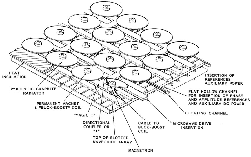
Figure M6. Assembly Architecture for the Magnetron Directional Amplifier in the Antenna Subarray. Two Power Modules are Shown. Microwave Drive and all References and Auxiliary Power are Inserted from the "Backbone" of the Subarray. The Array has Two Distinct Temperature Zones. The Top is Used to Radiate the Heat. The Bottom is Used for Mounting of Solid State Components
The power modules can prove to be very useful in that each radiating unit can intake DC power to produce RF microwave power. Since our photovoltaics array will provide a 10GW output, this DC power can be evenly split among the radiating units where each will perform its own DC to RF power conversion. This is beneficial because designing a magnetron which can intake 10GW DC input power is not easy to implement. A network of waveguides can then be used to combine all generated microwave power by each radiating unit. The combined microwave power can delivered to the transmitting space antenna to transmit the power back to earth.
The size of the current radiating unit is 77.48cm by 36.83cm.