Antennas & Coverage
The subsections below summarize the proposed antenna designs and specifications for this experiment. Thorough trade studies will be conducted during Phase 1 to analyze the cost-performance tradeoffs of the antennas and main link budget drivers (LNAs + PAs) to ensure the optimal cost-minimizing link design.
Earth Station Antennas
The primary design drivers for the Earth station antennas are robustness, reliability, and cost. Identical but separate antennas will be used for the W-band uplink and the V-band downlink to maximize technology re-use and to minimize costs. Engineers at NASA Glenn Research Center recommend a minimum Earth station receive antenna beamwidth of 0.8 degrees to ensure robust operation. This beamwidth is sufficiently large to prevent geostationary satellite movements from affecting the power measurements, so antenna tracking mechanisms will not be required [1]. This relatively large beamwidth results in a small antenna which is both simple to manufacture and is less expensive than larger antennas. Additionally, small antennas can be fabricated with lower surface roughness and therefore higher efficiency than larger antennas.
We propose using circular Cassegrain reflectors with diameters of 30 cm each for the Earth station receiver antennas. The gain and beamwidth of these reflectors can be calculated from the following equations:
and
Where ηeff is the antenna efficiency, D is the directivity, Aem is the aperture size in meters, and λ is the wavelength in meters. Calculated antenna gains and beamwidths for the main frequencies of interest are contained in Table 1. A nominal antenna efficiency of 45% is assumed for these calculations, per similar proposals in the literature [2]. The proposed receiver antenna clearly satisfies the recommended beamwidth requirement and will help ensure low-cost, robust Earth stations.
Table 1. Estimated Directivity, Beamwidth, and Gain of Proposed Earth Station Antennas
Satellite antennas
In order to provide experimental flexibility, the proposed W- and V-band antennas on the satellite will be designed to have a footprint covering the majority of CONUS from a geostationary orbit centered above 100 degrees West longitude, as specified in the BAA. This footprint requirement sets the size of and limits the peak gain/directivity of the antenna. We propose using an elliptical reflector similar to that proposed in [3]. Coverage of CONUS from GEO necessitates an elliptical beam with a beamwidth of roughly 6 degrees (horizontal) by 3 degrees (vertical). This results in an elliptical aperture size of around 13λ (horizontal) by 26λ (vertical) [3, 4]. We selected a horizontal width of 100 mm and a vertical width of 40 mm to satisfy these requirements. A nominal efficiency of 45% is chosen assumed per similar experiments [2]. The estimated directivity and gain of the antenna across the frequencies of interest are listed in Table 2.
Table 2. Estimated Directivity and Gain of Proposed Beacon/Transponder Antennas
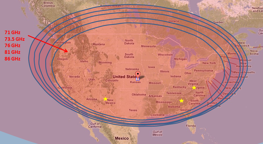
An online tool [5] was used to simulate the expected antenna footprint from GEO across frequency, as shown in Figure 1, along with the locations of the proposed Earth station locations. The concentric circles in Figure 1 mark the 3 dB footprint for each frequency of interest. Clearly, the selected Earth station locations fall well within the beamwidth of the proposed antennas for all frequencies of interest. The large footprint allows for possible future experimentation using different Earth station locations across the majority of CONUS.
Figure 1. Simulated beacon/transponder antenna coverage map across the frequencies of interest.
The same antenna design will be used for the W-band receiver and the V-band transmitter to maximize technology re-use. Separate antennas will be used for the transmitter and the receiver to ensure high isolation between the two paths and to prevent the use of lossy front-end switches and/or circulators. Using separate antennas will increase the payload size and weight, but these antennas are relatively small so the size/weight penalty should not be large. Each antenna will be equipped with a radome to protect against particulate damage that would degrade the radiating efficiency over time.
References:
[1] R. Acosta, J. Nessel, R. Simons, M. Zemba, J. Morse, and J. Budginer, “W/V-Band RF Propagation Experiment Design,” 18th Ka and Broadband Communication Conference, Ottawa, Canada, Sept 24-27, 2012.
[2] A. Jebril, M. Lucente, M. Ruggieri, T. Rossi, “WAVE – A new Satellite Mission in W-Band,” IEEE Aerospace Conference, pp. 870-879, March 2005.
[3] R. N. Simons and E. G. Wintucky, “Q-band (37-41 GHz) Satellite Beacon Architecture for RF Propagation Experiments,” IEEE Antennas and Propagation Society International Symposium (APSURSI), July 2012.
[4] T. Pratt, C. W. Bostian, and J. E. Allnutt, Satellite Communications, 2nd ed., John Wiley and Sons: New Jersey, 2003, pp. 117-118.
[5] http://www.satellite-calculations.com/Satellite/footprintplotterV1.php


