Hardware
Transmitter
High level design of Transmitter proposed for this link is based off of the Perla-W Transmitter architecture used by Lucente et al. in (REFERENCE); a terrestrial communications link at 95.453 GHz. As this new proposed system is to operate between 71-76 and 81-86 GHz with bandwidths up to 20 MHz, a similar transmitter will meet the goals of this system.
In this transmitter the base IF signal is generated by a software defined radio, made up of a Direct Digital Synthesis (DDS) system with amplification and harmonic filtering. By using DDS, the modulation schemes and bit rate of the communications link can be changed and updated based on the current test plan. The output of this stage is mixed up to an intermediate frequency, filtered and amplified, then mixed up a final time before being amplified by the Travelling Wave Tube (TWT) amplifier that outputs to the antenna for transmission. The use of a TWT amplifier implies a large amount of power consumed for this transmitter. However, as the scope of this proposal excludes power concerns for the until the spacecraft is selected in a later phase (See Table 2 in BAA), this amplifier was chosen based on its excellent performance and ability to provide a large power output that will be necessary for the system to have a Link Margin large enough to adequately characterize the rain losses at these high frequencies.
It is important to note that the oscillator frequencies are tunable, allowing for the carrier frequency of the system to be changed across the uplink and downlink band for characterization of the multiple frequencies. By using two separate up conversion stages, the carrier frequency can be tuned in large steps by the lower frequency Local Oscillator (LO) and in smaller steps by the higher LO. These carrier frequencies are to be changed according to the test plan(s) by commands transmitted to the satellite and all ground stations on the satellite’s backbone communications link; thus ensuring that all transmitters and receivers are operating with the same carrier frequency. Finally, the backbone communication link available is to be used to add complexity in coding and modulation schemes to the software defined radio as testing continues.
Receiver
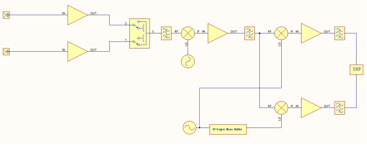
High level design of the Receiver proposed for this link is based off of the Perla-W wideband receiver architecture used by Lucente et al. in (REFERENCE); a terrestrial communications link at 95.453 GHz. As this new proposed system is to operate between 71-76 and 81-86 GHz with bandwidths up to 20 MHz, a similar receiver will meet the goals of this system.
The receiver shown in Fig. X is a representation of the receivers to be placed at ground stations. These receivers are designed with two receive antennas, on mounted for vertical polarization, the other for horizontal; both of these antennas have a gain of 51.4 dB in the proposed frequency range. The receiver will switch between these two antennas based on the test plan(s) for the current experiment.
The Low Noise Amplifier (LNA) used in this receiver proposal is a Commercial Off the Shelf (COTs) LNA manufactured by Hittite with a Noise Figure (NF) of 5.
For either horizontal or vertical operation, the receiver has two mixing stages before the signal is brought into a system for Digital Signal Processing (DSP.) The second stage of down conversion splits the signal into In Phase and Quadrature (I and Q) components before the DSP stage by shifting the LO by 90 degrees for one of the mixers that the signal is sent into.
It is important to note that the oscillator frequencies are tunable, allowing for the carrier frequency of the system to be changed across the uplink and downlink band for characterization of the multiple frequencies. By using two separate up conversion stages, the carrier frequency can be tuned in large steps by the lower frequency Local Oscillator (LO) and in smaller steps by the higher LO. These carrier frequencies are to be changed according to the test plan(s) by commands transmitted to the satellite and all ground stations on the satellite’s backbone communications link; thus ensuring that all transmitters and receivers are operating with the same carrier frequency. Finally, the backbone communication link available is to be used to add complexity in coding and modulation schemes to the DSP block of the receiver as testing continues.
Components
Here is a list of the datasheets of all the components used.