Link Budget
Friis transmission equation
The Friis transmission equation is used in telecommunications engineering, and gives the power received by one antenna under idealized conditions given another antenna some distance away transmitting a known amount of power. The formula used to estimate the link budget is as follows
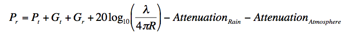
- Where, Pr is the power received by the reciever.
- Pt is the power transmitted by the transmitter.
- Gr and Gt are the gaines of the Receiver and the transmitter respectively. Since we have used the same antenna for the transmitter and the receiver, Gr = Gt = 51.4 dB.
- Atmospheric attenuation is estimated to around 2.6 dB.
- Rain Attenuation is calculated individually for all of the three locations.
Link Budget Calculation
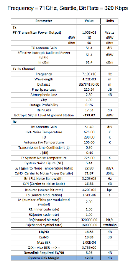
Link budget calculations for the proposed system were completed following the general template used by Lucente et with simplifications implemented by assuming gain defined by selected antenna to be constant over the bands of operation and antenna pointing to be ideal.
Based on the use of a Travelling Wave Tube (TWT) transmit amplifier proposed, combined with the antenna chosen, an Effective Isotropic Radiated Power (EIRP) near 61.4 dBW is expected.
The transmit and receive channel Free Space Loss was estimated from 71-76GHz and 81-86GHz with a distance between the earth station and antenna calculated based on geostationary orbit. In addition to Free Space Loss, the Link Budget used in this proposal includes an estimated Rain Loss Factor (RLF) based on results based on the ITU recommendation. These RLFs were calculated for the ground stations located in Seattle, WA, Columbus, OH, and Atlanta, GA for an outage probability of 0.1%; locations selected for both latitude and Rain Fall Zone differences. Using these RLFs in conjunction with the calculated Free Space Loss calculations, an estimate of the transmit and receive channel loss for the duration of the testing of this proposed satellite was used in order to predict link margins for different tests.
Furthermore, once the Gain to Noise Temperature Ration (GT Ratio) was calculated based on chose antenna and Low Noise Amplifier (LNA), the Carrier to Noise Ratio (CNR) was estimated for a wide range of Bit Rates on an uncoded BPSK system. Finally, the System Link Margin (SLM) was calculated based on a Bit Error Rate (BER) of 0.0001.
Finally, using the information described above, summary tables were generated for each ground station location, for 0.1% outage probability, a max BER of 0.0001 at various Bit Rates were generated. A final table of SLMs for a clear day situation was generated to show that for all proposed frequencies and data rates, the SLM is sufficient for communications.
Interactive System Link Margin Calculator
Select the operating frequency, location and data rate from below to calculate the Sytem Link Margin and determine at what datarates, the link breaks!
Frequency:
Location:
Data Rate:
System Link Margin : 3.07dB
Supported Data Rates
Baseline
Baseline System Link Margins for the frequency bands of interest at various data rates can be seen below. Notice that with zero rain attenuation, an estimated 164 Mb/s link is possible with encoded Binary Phase Shift Keying (BPSK) transmitted messages.
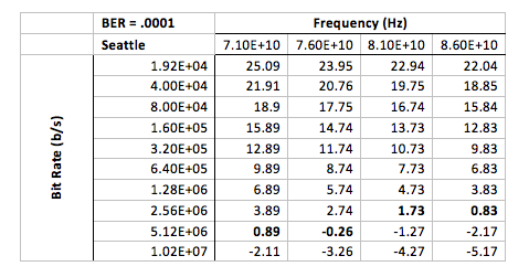
Seattle
Notice that the point where the SLM is insufficient is different for the uplink and downlink for this location when rain attenuation estimates are taken into account. With this a priori knowledge of potential system performance it is recommended that test plans take into account testing uplink and downlink separately until know working data rates for both channels are known before attempting bi-directional testing. The estimated maximum Bit Rate for both uplink and downlink frequencies for this location with rain effects at 99.9% reliability is 2.56 Mb/s.
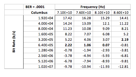
Columbus
Similar for to Seattle, the data rates for uplink and downlink are likely different when rain effects are taken into account. Notice that the estimated maximum Bit Rate for both uplink and downlink frequencies for this location with rain effects at 99.9% reliability is 320 kb/s.
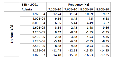
Atlanta
In calculation of SLMs, Atlanta turns up as the harshest location for testing for the proposed system. The estimated maximum Bit Rate for both uplink and downlink for this location with rain effects at 99.9% reliability is 160 kb/s.