Final project: The Martian Network
Mars Satellite <-> Mars Terminal
The link between terminal on Mars and one of the satellites is
quite similar to the link between the satellites. It should be kept in mind,
that the satellites in the polar orbit are not stationary with respect to the
Martian surface therefore a terminal in the polar regions will have to be able
to swich between satellites, if it wants to maintain un uninterrupted link for
longer time. To overcome this problem they are equipped with two dish antennas,
that are able to track the position of the satellite and adapt their position so
they point directly to the satellite in their line-of-sight. In case a terminal
sees multiple satellites, it communicates with the one that it sees at the
highest elevation angle. Also, if it is detected that the elevation angle is
approaching the minimum value, the terminal tries to switch to the second
antenna, since the current satellite will soon disappear from the area seen by
the terminal.
The allocated frequency bands are 5.75-6.25 GHz for the uplink and 6.50-7.00 GHz for the downlink.
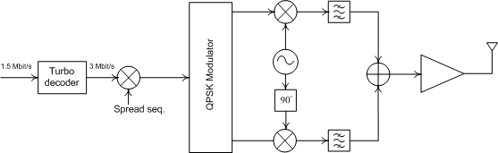
Pulse shape stays the same as in the satellite <-> satellite link and so are the modulation, spreading properties, and channel coding. With this in mind the block diagrams of the receiver and the transmitter can be with the following two figures.
The block diagram of the terminal transmitter.
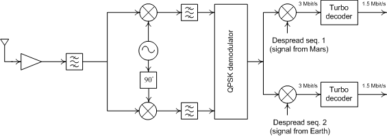
The block diagram of the terminal receiver.
Terminal -> Satellite
Each terminal has one spreading sequence assigned to it for use
and it stays the same all the time, while the despreading codes that should be
used for incomming signals are communicated to the terminal in the signaling
phase. Each terminal must have the ability to maintain one link with Earth and
one with another terminal on Mars, which is shown in the block diagram of the
receiver.
We mentioned that two antennas are implemented on the terminal side. Only one of them is active at a time during the communication, however the terminal has the ability to switch between them (handover). This ability also provides additional flexibility in the hilly terrain, where a line-of-sight can often be obstructed by hills, mountains, etc. Both dish antennas have identical specifications: 1 meter in diameter, efficiency of 0.9 and they provide 36.5291 dBi and 35.5060 dBi gain at 6.00 GHz and 6.75 GHz, respectively. The terminal transmits the signal with the power of 1 Watt.
The antenna on the satellite is the same as the one used in the satellite <-> satellite link. The physical temperature at the satellite antenna was assumed to be 150 K and the device temperature of the low-noise amplifier 40 K.
The minimum tolerable elevation angle is 10 degrees, therefore the maximum distance between the satellite and the terminal can easily be obtained by using the rule of sines (see Pratt et al. - pages 406, 432) and results to be 19531 kilometers.
With these data it can be calculated that the C/N ratio (see how C/N was calculated) at the receiver on the satellite is 7.0891 dBi. It has to be taken into account that the signal from the terminal will not always fall onto the satellite's antenna at an optimal angle. Consequenlty, we take the gain at the half-power bandwidth angle (41.5266 dBi - 3 dBi = 38.5266 dBi). The maximum number of interferers here is 49 since there can be up to 50 terminals communicating with one satellite.
Satellite -> Terminal
The satellite transmits the signal to the terminal with the same power at the frequency 6.75 GHz. The block diagram of the satellite transmitter and receiver are the same as in the satellite <-> satellite link. Other parameters are
dish antenna (satellite) has diameter 2 meters and efficiency 0.9; peak gain 42.5497 dBi at 6.75 GHz
physical temperature seen by the terminal: 300 K (worst case)
terminal low noise amplifier device temperature: 60 K
Again, the signal from the satellite will not always be entering the antenna on the terminal at an optimal angle, therefore we take the gain at half-power bandwidth angle (35.506 dBi - 3 dBi = 32.5497 dBi). The terminal will not necessarily receive the peak signal from the satellite either - therefore 42.5497 dBi - 3 dBi = 39.5497 dBi should be taken as the trasmit antenna gain. Signal power at the transmiter in the satellite is set to 10 Watts. The resulting C/N ratio (see how C/N was calculated) is 4.1045 dB -- well over the threshhold value for the target bit error rate. The maximum number of interferers is 99, since in the worst case the satellite will transmit 100 signals at the same time (50 from earth, 50 from terminals -- all terminals are served by the same satellite, all terminals communicate with Earth and another terminal).