|
LRT |
 |
|||||||
| Table of Contents |
Communications SetupThe next section describes the workings of the internal radio components required to operate the satellite relay network efficiently. Since use of the Deep Space Network was planned, there were certain limitations placed on the designers of the satellite link to meet a minimum level of Signal-to-Noise Ratio (SNR) and operating bandwidth. The first step was to determine the specs of maximum allowable frequency which could be received on Earth using the existing DSN before factors such as surface roughness would limit the dish. To avoid band of frequencies from 1.40-1.43 GHz, 4.9-5.0 GHz, 10.6-10.7 GHz, and 15.3-15.4 GHz, which would interfere with radio telescopes on the Earth, we chose the transmission band to start at 15.4GHz.
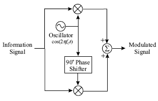
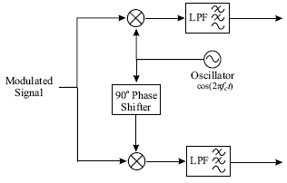
Modulation SchemeQAMAs with all modulation schemes, QAM conveys data by changing some aspect of a carrier signal, or the carrier wave in response to a data signal. In the case of QAM, the amplitude of two waves, 90 degrees out-of-phase with each other are modulated to represent the data signal. The following diagrams represent the topology of the transmitter and receiver architecture.
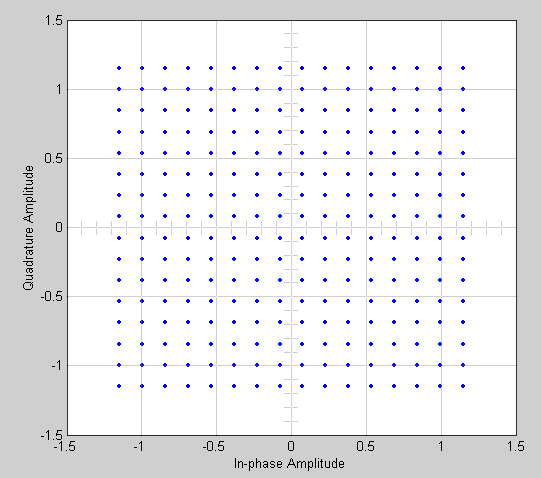
HardwareAs shown, the oscillator will need to be able to operate without too much deviation from the proposed frequency, and since the center frequency is less than 20 GHz there shouldn't be a problem finding this hardware. Additionally, not shown here, we will need to use an Analog-to-Digital Converter on the transmit side and a Digital-to-Analog Converter on the receive end to be able to process the signal electronically. Simple IC designs are available to meet the specifications of this project. Signal Constellation
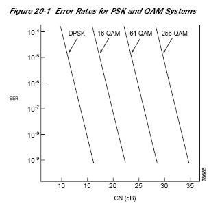
256-QAMThe modulation scheme selected to use with this design was 256-QAM. Appropriately, since we chose a fairly high order modulation type, the amount of transmit power was increased, however, due to the fairly linear path taken back from the signal source, the savings in path loss from a less direct path could compensate for such a tradeoff. This design also had a high spectral efficiency of 6 bits/Hz. The Bit-Error-Rate (BER) designed for at the receiver was 1e-6. This provides almost error-free transmission which is considered acceptable for space communication. Given the modulation and BER, a direct lookup could be done for the energy (per bit)-to-noise ratio (Eo/No) or Carrier-to-Noise Ratio (C/N or CNR). A chart can be seen below for uncoded 256-QAM.
As seen, the uncoded 256-QAM scheme would require a CNR of around 30dB. This would actually increase the power budget beyond the scope of most funding for satellite programs. We therefore have chosen to include some Forward-Error-Correction (FEC) to decrease the requirements on signal fidelity we need at the receiver while slightly increasing the amount of data to transmit.
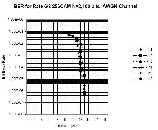
Turbo CodesThe FEC scheme chosen to use with this design was Turbo Coding. Turbo Code provides the highest amount of coding gain, or lowering of the required C/N, of all the currently existing FEC types. The rate 6/8 Turbo Code using 2048-bit Interleaver was used for the current design. A chart for the coded Eo/No can be seen below.
The required Eo/No to achieve a BER of 10-6 is now 14dB. The SNR was computed from this value by adding a factor equaling the Data-rate/Bandwidth. The result was an SNR of about 23 dB. The coding gain from using this form of Turbo Code was therefore around 7 dB.
QuantizationThe quantization level chosen was derived from the fact that in radio astronomy typical Radio astronomy intensity level for brightest source was around 10-24 W/Hz*m2. Taking a slightly lower value than the brightest source, we have used a value of 10-23 W/Hz*m2 in the calculations for received power at the moon base. The calculation can be seen below. Received Power= 10*log10(Apperture_Effeciency*Intensity Value*Bandwidth*(pi*Radius2)) Pr=10*log10(n*Intensity Value*B*(pi*R2)) [5] From the received power, we can derive the SNR by adding in the receiver noise. The following simple calculation is used to arrive at the quantization can be seen below. SNRQ=6N [6] The quantization used for this design was 6 bits. While this amount usually is not an issue, with the high data-rate associated with the communications system herein, this did play an important role in choosing the other factors in the design, such as the modulation scheme.
Bandwidth CalculationsOnce the quantization rate is determined, this value alongside the Nyquist Frequency will evaluate to the initial data rate. The Nyquist Frequency comes from the Nyquist Criterion which says:
In other words, Freq=2*Fmax. [7] Given that our band of interest spanned from 1-4 GHz, the Fmax was 4GHz, meaning the data would need to be sampled at 8 Giga-samples/sec. Multiplying by the quantization rate of 6 bits/sample gave an initial data-rate of 48 Gbps (shown below). uncoded data rate (bits/sec) = N (bits/sample) * Nyquist rate (samples/sec) [8] The coded data rate, using a 6/8 rate Turbo Code algorithm, was therefore 64 Gbps. This is an enormous amount of data to transmit through any communications channel, much less through space at such large distances. Allowances must be made in terms of power budget and/or time to transmit in the design of such a system. Since the design used a 256-QAM modulation scheme, the number of bits/symbol was 8. While this allows for much more data to be compressed into a smaller amount of bandwidth, it creates a need for a higher fidelity signal at the receiver in terms of SNR. This was earlier accounted for. The calculation to determine the symbol rate is as follows. Symbol rate (symbols/sec) = Data rate (bits/sec) / (bits/symbol) [9] The symbol rate calculated was 8 Giga-symbols/sec. This number was then used with the pulse shape described in the next section to arrive at the final transmitted frequency bandwidth. The formula used is shown below. Bandwidth=(1+rolloff)*Symbol rate [10] The computed bandwidth was 8.16 GHz. After knowing the start-frequency (15.4 GHz) and the bandwidth, it is possible to calculate the stop-band. This value came out to be 23.56 GHz.
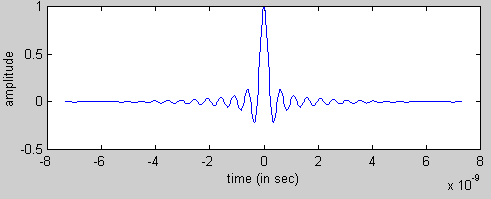
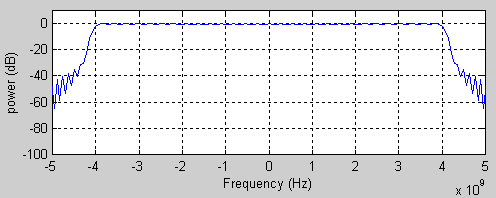
Pulse ShapingUsing QAM, it was decided to use a very short time domain pulse which would constructively use as much of the allotted frequency bandwidth as possible. To achieve this, we used a raised cosine pulse with an extremely small roll-off factor of .02. While this factor would be hard to implement, the budget saved from a shorter bandwidth spectrum was seen to outweigh this tradeoff. The diagrams below show the time domain raised cosine pulse and the frequency domain information at baseband. This could be "mixed-up" to the appropriate frequency using the topology shown in the above section.
|
|||||||
