SELENESafe Exploration for Lunar Environments: Navigation Experts |
| Home | Synopsis | Antenna Design | Communication system | Location System | Power System | Timeline & Budget | References | About |
|
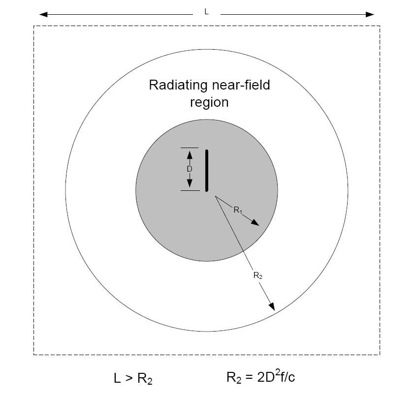
A simple quarter-wave monopole antenna was chosen to be designed as the omnidirectional antenna of choice. So that our designed system would be compatible with the large quantity of hardware that current exists for wireless applications, we selected to operate at an RF of 2.4 GHz. The antenna was constructed using a large, copper plate as a ground plane, with a thin copper rod as the radiating element. The size of the copper plate needed to have an effectively infinite groundplane at the selected operating frequency. To determine this size, the size of the near-field region needs to be calculated. The method needed to accomplish this is illustrated in Figure X [1]. The radius of the near-field region is defined by the radius R2 which depends on the wavelength of the signal as well as the height of the radiating element. The length of the square copper plate needs to be greater than this calculated value.
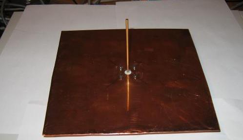
Given that the antenna is a quarter-wave monopole operating at 2.4 GHz, the value of the parameter D is calculated to be 31.3 mm. From this value we calculate the radius of the near-field region of the antenna to be 15.6 mm or equivalently 0.62 inches. The size of the square copper plate was chosen to be 6 inches x 6 inches, well above the value of the near-field radius. The completed antenna is shown in the Figure below:
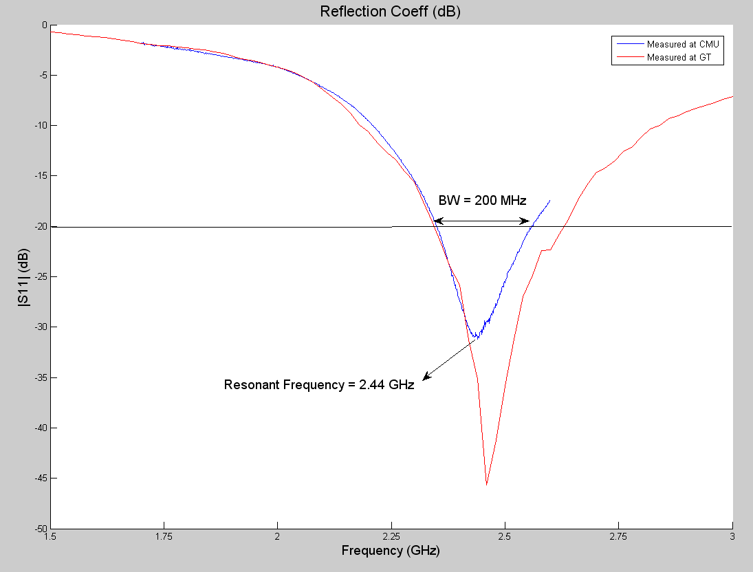
To verify that the antenna radiated at the correct frequency, the reflection loss across a frequency span of 4 GHz (1 Ghz to 5 Ghz) was measured at the Georgia Institute of Technology. The reflection loss was also measured at CMU, where the range tests were also performed. The results of these measurements are shown in the figure below.
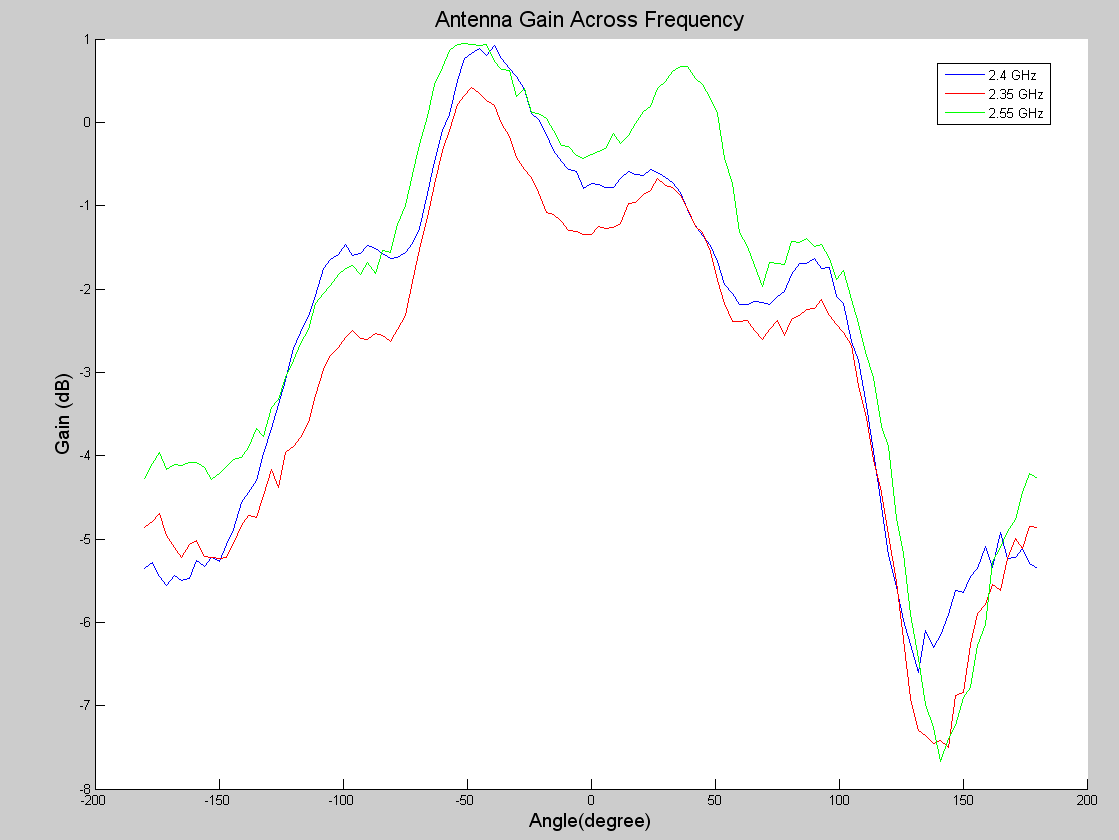
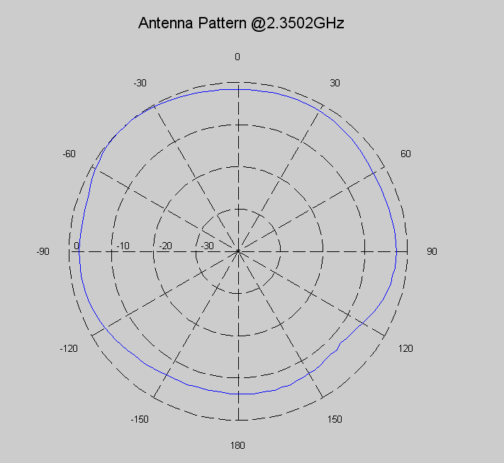
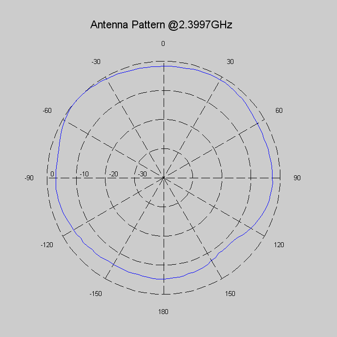
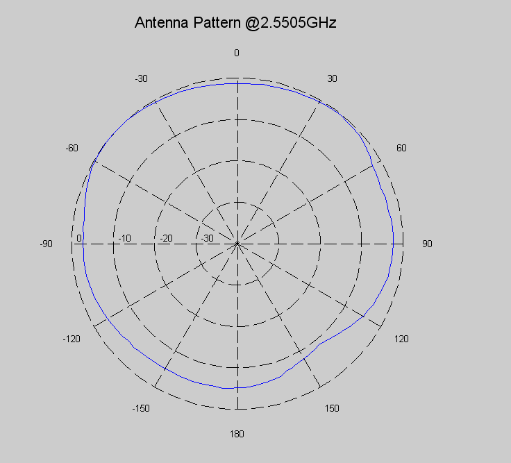
As is evident from the figure, the resonant frequency is very close to the designed value of 2.4 GHz. Additionally from the measured reflection loss the antenna bandwidth can be determined (taking the bandwidth to be frequencies which have a reflection loss greater than -20dB) and is reported to be just greater than 200 MHz. From the range at CMU, the engineers at SELENE were able to measure the antenna gain pattern across varying frequency and orientation; however, at the time of measurement the antenna was mounted with a slant, which we believe skew the measured results. The following Figure shows the reported gains at three different frequencies, the two edges of the antenna bandwidth and the resonant frequency.
As can be seen from the figure, the antenna has a relatively large variation of gain across azimuth angle. For visualization, the polar plots of gain for these three frequencies are included below.
The table below shows the averaged gain across angle for these three frequencies.
Despite these average antenna attenuations, the engineers at SELENE are confident that the next stage prototype will provide a relatively average gain of 0dB. As such, this is the value that has been used for all link budget calculations provided herein.
|