


A simple MATLAB code was implemented to simulate the basic working of the modulator and the demodulator.
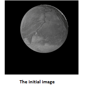
This gray scale image is first converted into a black and white image for processing. The picture after being converted into black and white is shown below.
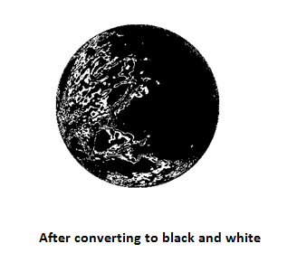
This image is then passed through the modulator. At the receiver end the data signal is passed through the demodulator. The output obtained from the demodulator is shown below.

We have simulated only a basic design of a modulator/demodulator. The same shall be extended to colored images with more complexity. The code for this can be downloaded from the downloads page and is titled “QPSK Mod/Demod Example.”