Resiliency - Lander (page 2 of 2)
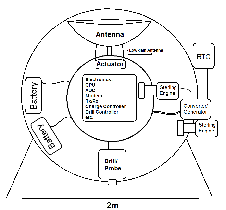
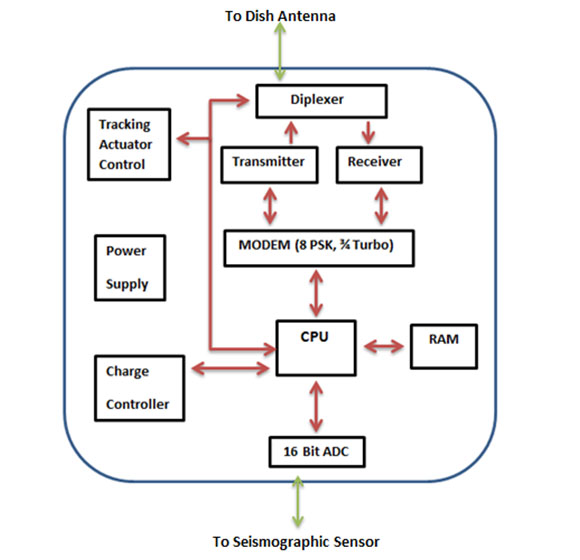
A cross-section of the lander can be seen below. The lander will be powered by a combination of Radioisotope Thermal Generators (RTG) and batteries. This is discussed more in the “Power” section of the website. The RTGs will be attached to the outside of the lander and power all the electronics as well as reverse sterling engines that will cool the craft. The batteries will be slowly trickle charged for a period of about 8 hours, them used to boost the transmit power for the antenna. There will be an inner shell that houses the electronics. It will be approximately 0.5 meters in diameter. Due to the successive sterling engines used for cooling, the air in this inner shell should be around 30°C. This temperature should be adequate for the necessary electronics. The inner shell will also house actuators that will function to slightly move the antenna dish to follow the satellite. At the bottom of the lander will be the drill and seismic sensor. The drill will exit the shell and enter Venus, and permanently embed the sensor in the ground.


Descent
Shell
During
descent, the lander will be enclosed in a large shell. The shell will
also be
made of a Nickel-based Superalloy; however will be thinner than the
lander’s
sphere. Once the lander reaches certain altitude, parachutes will
deploy from
the shell to slow the descent. Another set of parachutes will remove
the top
half of the shell, and a final set will remove the lander from the
bottom half
of the shell, allowing it to land safely. (Example of landing can be
seen at: http://www.russianspaceweb.com/venera75.swf)
