MICROMETEORITE ENVIRONMENT
Characterization of Micrometeoroid Environment
Along with natural space dust and micrometeorites there's also been an increase in
manmade space debris. Impacts from these small particles can be dangerous if their
velocity is extremely high. The average density and velocity of micrometeoroids
are 0.5 g/cm3 and 20 km/sec respectively and space debris or manmade debris is 2.8
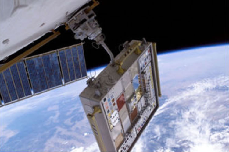
g/cm3 and 10 km/sec. The micrometeoroid and orbiting impact damage recording system
was implemented after the Columbia space shuttle accident of 2003 by the University
of Dayton Research Institute. This study was conducted at LEO to monitor the space
craft's wing and impacts that it encountered. This was deployed on the International
Space Station to conduct the study on micrometeoroid impacts. Micrometeoroid impacts
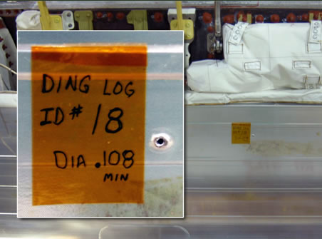
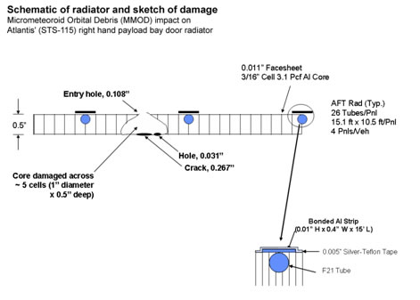
have been observed frequently in space including
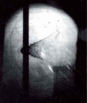
on STS-115 Atlantis. Also in the X-ray telescopes aboard the
XMM-Newton observatory during revolution #156 more than 30 of the 150,000 pixels of
the 6cmx6cm array lit up because damage to the mirror causing changes to the focal
plane picked up by the
pn-CCD detector array on board.
Current Knowledge of Micrometeoroid Impact Probability on Hardware
Because of this the probability that such events is dependent on the concentration
of particles which determines the probability over a set area that a material may
have an impact in orbit. The probability of impact over a given area is also known
as the micrometeoroid fluence and there are many models that express this fluence
levels shown here is the "Grun" flux model.
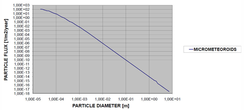
The total number of impact N is linked to:
The particle Flux Fx
The Impact area A
The exposition time Ti
According to the following equation
N=Fx*A*Ti
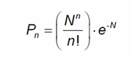
The Probability of having n impacts over an area A follows the Poisson distribution
bellow. Where P0 would be the probability of having a single impact, P1 would be
the probability of having 1 impact and so on.
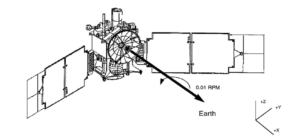
Also the leading edge of the orbiting satellite has a higher rate of impact then
the trail side and so therefore must have better protection. Figure bellow shows
the Mars Global Surveyor (MGS) project. The fluences for each surface were
calculated. The side that faced the Mars orbiting velocity the +Y side. Since this
is the leading edge it was calculated to have 20 times larger flux than the
trailing edge of the space craft.
For orbiting the earth the Grun model must take into account the earth shielding
factor, the gravitational focusing factor increasing the flux, and the directional
factor taking into account of the orbital orientation and velocity of the orbiting
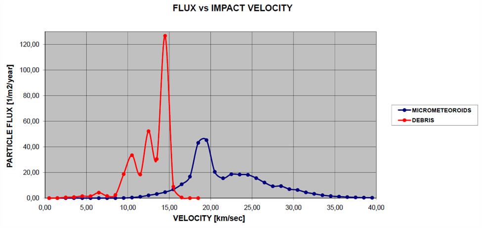
surface. NASA has additional to this model broken the impact particle into 2
categories; the debris or manmade particles with the micrometeorite flux. As it can
be seen the micro meteoroid has a much wider
velocity distribution than the manmade debris.
Damage Models of Impact
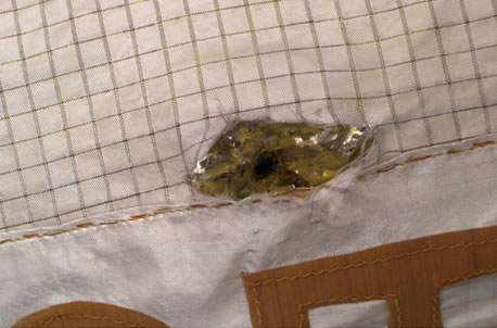
These impacts occur at hypervelocity mode or the particles exceed the sound
propagation velocity in the material. This causes damage much greater then
subsonic impacts. Due to this great impact the particle can cause the material
to melt and/or vaporize causing a pressure wave which one or more of the
fallowing damages, surface damage, spalling or punching also see supplementary
photos to the right. Structural damage can be seen in penetration of spacecraft
walls, penetration of pressurized vessels such as fuel tanks, cutting of cable
and other electronic interconnects.
Single Wall Model or Front Wall
The Fish-Summers Equation can express the thickness needed for a single wall as
long as the projectile material is aluminum and the plate material is
magnesium-lithio, aluminum, copper-beryllium alloys and the impact velocity is
from 0.5 to 8.5 Km/s. According to this model the plate thickness t (expressed in cm)
is proportional to the particle mass m (g), the particle density p (g/cm3)
and the impact velocity V (Km/s) as shown in the equation:
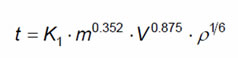
Where K1 is a constant depending on the plate material and is around 0.57 to 0.7.
This equation gives the minimum value of t needed to avoid spalling
Double Wall Model or Trailing Wall Model
Under the same conditions as above the trailing edge of the spacecraft wall minimum
thickness needed can be expressed by the bellow equation:
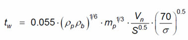
- tb is the bumper thickness (cm)
- ρp is the particle density (g/cm3)
- ρb is the bumper density (g/cm3)
- mp is the particle mass (g)
- S is the distance (cm) between the bumper and the rear-wallmper and the rear-wall
- σ is the rear-wall yield stress (ksi)
Conclusion
The lack of consider micrometeoroids on a space mission especially in the size and scale
of the space solar power would be extremely costly. It is very likely that an event
of some significance would impact one of the orbiting satellites and possibly more
causing a catastrophic failure. In addition to this, the system performance would be
degraded by a percentage related to the flux patter in the orbiting path and the
duration of the mission. This will be critical because in order to achieve profitability
the satellites must stay operational for at least 10 years to break even. With the above
information care should be taken in the design of components protecting them. Also
enough margins in the solar power arrays should be implemented to maintain adequate
power for the satellite. There are in existence several ground test facilities that
are capable of testing the required material needed for spacecraft protect. They use
a Van De Graaff Accelerator or the Light Gas Gun. These methods have been used for
testing such missions as Pegasus, Explorer 16, Explorer 23, HEOS 2, Pioneer 8,
and Pioneer 9.
