Hardware Design Considerations in Transponder System
For circuits in transponder system operating in W band and V band, normally their designs are based on MMICs (Monolithic Microwave Integrated Circuits). MMICs are fabricated by Gallium Arsenide (GaAs), Indium Phosphide (InP), or some other III-V compound semiconductor materials. Compared to Silicon technology which is mostly used in digital and low-frequency RF applications, these materials own higher cutoff frequency and lower noise. So MMICs are more suitable for satellite communication systems. MMICs are also well-suited for large arrays, which can facilitate our design if we want to realize large phased-array transceiver systems in the future.
There are mainly 5 important building blocks in a transponder system, including Low-Noise Amplifier (LNA), Local Oscillator (LO), Mixer, Power Amplifier (PA) and Filter. Since our team will design a thermal control system on the satellite, we don’t need to worry about the low-temperature impact on our transponder circuits, so we can re-use all the circuit techniques on the ground station to our satellite.
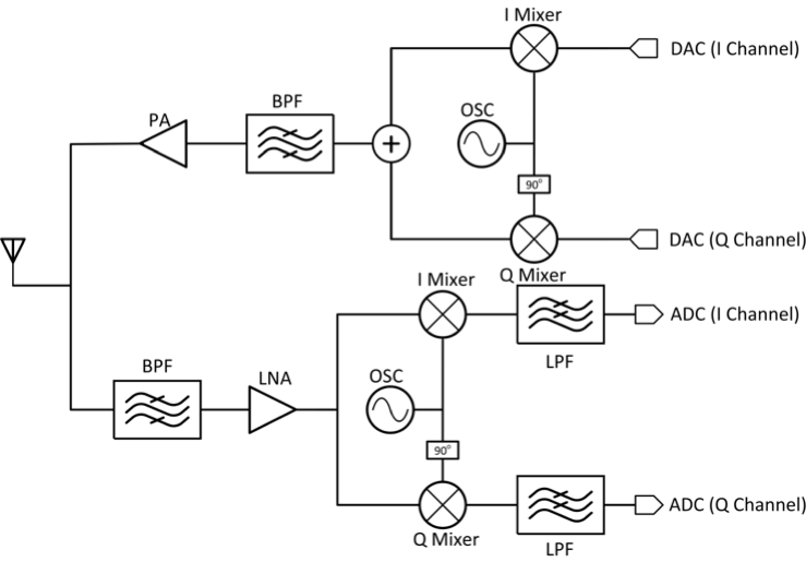
System Architecture
Low Noise Amplifier
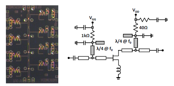
Two important requirements for LNA in our satellite communication system are to provide high gain and low Noise Figure (NF). Linearity is not an issue if we use QPSK or M-PSK modulation because all the transmitted and received signals have the same amplitude. Normally we should use multi-stage structure to achieve high gain. A design example in [1] is shown here to demonstrate the feasibility. In this example, the LNA was fabricated on 70nm GaAs technology. There are 4 stages to provide around 25 dB gain, while the NF is 2.7dB. Also the bandwidth of this LNA is 70-105 GHz, which covers the operation V & W band in our proposal.
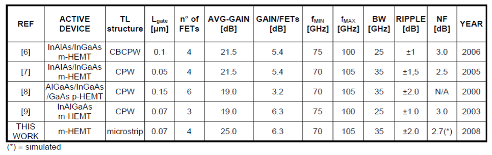
The following table concludes several MMIC LNA designs in V & W band. According to this table, above 20 dB gain and below 3 dB NF can be achievable for our satellite transponder circuits.
Local Oscillator
There are two major ways for LO design in W & V band system.
The multiplier circuits can be achieved by Schottky Barrier Diode (SBD) or by active circuits.
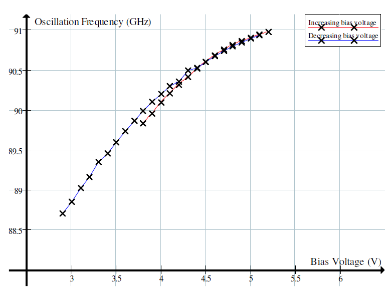
The center frequency of the oscillator can be tuned by changing the bias voltage. The following figure is the tuning range of the oscillator with respect to bias voltage in a W band receiver. [2]
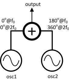
Normally, the fundamental frequency of Gunn oscillator is between 30GHz and 70GHz. So in order to generate LO signal in V band & W band, we need a doubler or extract the second order harmonic of the circuit as the following graph shows.
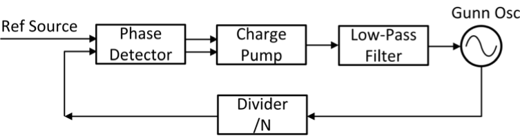
Gunn Oscillator can be phase locked to a microwave source. The following graph is the Phase Locked Loop (PLL) structure diagram of our system.
Mixer
Through literature review, there are three common ways to design a mixer for a satellite communication system.
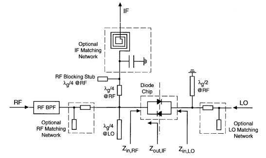
Due to its characteristics, SBD Mixer is suitable for up-conversion and down-conversion mixer on the satellite. The following figure is an example of GaAs SBD Down-conversion Mixer in [3], which achieves 7 dB conversion loss and better than 40 dB LO-RF isolation in W band. The DSB noise temperature is 650K.
When cooled below the critical temperature of the superconductors constituting the junctions, a SIS junction exhibits an extremely strong nonlinearity, which is very helpful for mixer design.
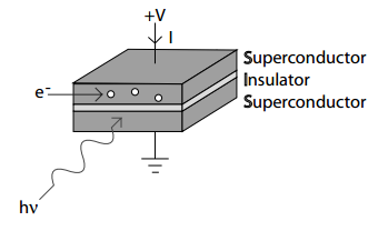
SIS Mixers own the best sensitivity in millimeter and submillimeter wave bands, so they are widely used in radio astronomy. The only disadvantage is that it must be operated in very low temperature (several tens K), so considering the cost, we just want to implement it in the ground station.
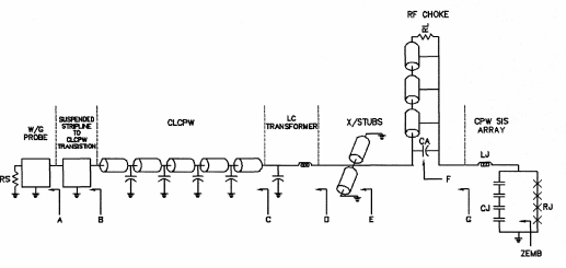
The following example [4] shows a SIS Mixer design which can fulfill the ALMA science requirements. The bandwidth of the mixer is 84-116 GHz, and the DSB noise temperature is 16-20K.
This kind of mixer has a wider bandwidth and requires less LO power compared with other mixers. However, the electrical stability is rather poor, and it is easy to saturate because of wide bandwidth. So it is not suitable for our satellite link.
Power Amplifier
In [5], people made a KPA with 2.0KW peak output power at 94.05 GHz. The efficiency is around 32%.
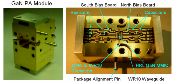
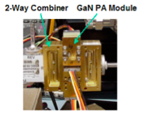
In paper [6], people reported a GaN W band PA. The highest measured output power from 4-way power combining is 3W with 10.2% PAE. According to our link budget, this kind of PA is definitely doable on the satellite.
Filter
In our system, we need several microwave band-pass filters. In general, most microwave filters are made up of one or more coupled resonators, so any technology that can be used to make resonators can also be used to make filters. The unloaded quality factor (Q) of the resonators will generally set the selectivity for the filter. The lumped-element filter works well at low frequencies, but in high frequencies people mostly use transmission lines and couplers to design filters, mainly because of distributed effect.
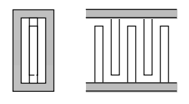
There are several ways to design microwave band-pass filters. [7]
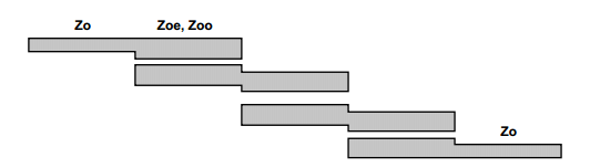
Because the lines are shorted at opposite ends, the structure takes the form of interlaced fingers, and is called an interdigital filter. This topology is straightforward to implement in planar technologies.
Reference
[1] W. Ciccognani, “Full W-Band High-Gain LNA in mHEMT MMIC Technology”, Proceedings of the 3rd European Microwave Integrated Circuits Conference
[2] http://gunn.winterwolf.co.uk/reports/interim
[3] S. Raman, “A High-Performance W-Band Uniplanar Subharmonic Mixer”, IEEE Trans. Microwave Theory Tech, Vol. 45, No. 6, June 1997
[4] S.-K. Pan, “A Fixed-Tuned SIS Mixer with Ultra-Wide-Band IF and Quantum-Limited Sensitivity for ALMA Band 3 (84-116 GHz) Receivers”,15th International Symposium on Space Terahertz Technology
[5] A. Roitman, “State-of-the-Art W-Band Extended Interaction Klystron for the CloudSat Program”, IEEE Tans. Electron Devices, Vol. 52, No.5, May 2005
[6] A.Fung, “Power Combined Gallium Nitride Amplifier with 3 Watt Output Power at 87 GHz”, 2011
[7] David Pozar, “Microwave Engineering”, third edition, 2005