For this experiment we need to observe the characteristics of the signal as it travels from the beacon on the satellite to the transponder on the ground station, and also as it traverses from the transponder back to the satellite.
Faraday Rotation
Faraday rotation causes a shift in the linear polarization of waves propagating through the ionosphere. The magnitude of Faraday rotation is dependent on the frequency of the signal and follows an inverse square dependence with frequency. Thus higher frequencies like the ones used in w/v band should see minimal effects from Faraday rotation. The following technique will measure the depolarization effects of the ionosphere.
We will measure the polarization angle with the following technique found in [x]. We will receive the wave with polarization angle α, with two crossed dipoles antennas X and Y. The h.f. output voltages of these polarization-sensing antennas would then be Ex and Ey. Next we will amplify and modulate these voltages with the cosine and sine of angle β, respectively. This angle will be created by a direct voltage and a function generator which will compute the cos(β) and sin(β). Finally a sum of the two voltages is computed and denoted by Ec. We can then vary the angle β until the maximum Ec is found, this indicates that the angle β is equal to α, thus the polarization angle is determined. The difference between this angle and the angle of polarization of the transmitted signal would give us the Faraday rotation. A figure of this scheme depicted in [1] is given.
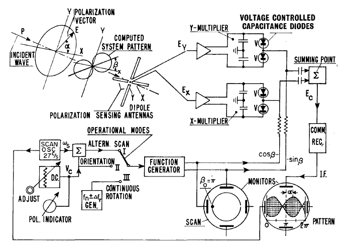
[x] Vogt, Gottfried; , "An analogue polarization follower for measuring the Faraday rotation of satellite signals," Radio and Electronic Engineer , vol.28, no.4, pp.269-278, October 1964
Signal Attenuation
Measurements of signal attenuation can be conducted by observing the power of the received signal during different periods of the day and also under varying atmospheric conditions. With the knowledge of the power of the outputted signal from the beacon on the satellite we can compute this attenuation. Ionospheric effects can be observed through clear day observations on the signal attenuation during periods of varying ionosphere depths. Each region of the ionosphere experiences changes in height between night and day, the primary effects is the lower electron densities experienced at night. Rain attenuation can be recorded with the metrological information such as cloud heights and rainfall rates. The value of the effective length of the signal path will be determined based on the location of the satellite, the ground station, and the height of the rain clouds. With this information and the recorded values of attenuation during these periods a model can be created which depicts the effects of clouds and rainfall rates on the w/v band signal.
Phase Distortion
The phase distortion which is commonly caused by noise, such as thermal noise or noise added by the ionosphere, can be found by the Error Vector Magnitude Measurement (EVM). With this experiment we will know the phase and amplitude of the signal transmitted, using the constellation of QPSK we will then be able to use EVM to find the difference between the phase and amplitude of the sent and receive signals. The following figure shows how this process is conducted:
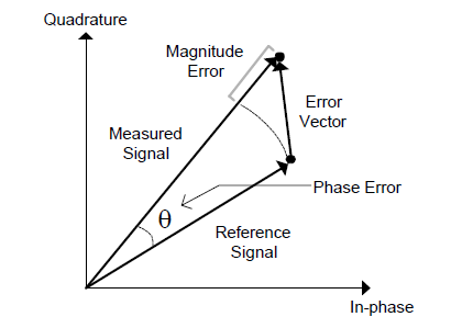
CVM detection diagram
The phase distortion is thus the angle between the measured and reference signal.
BER
Bit error rate for a signal is the probability that the received signal is offset in amplitude or phase by a certain amount which would cause the resulting detection of the signal to be incorrect. In modulation schemes such as BPSK and QPSK, the bit error rate is affected solely by the phase of the signal, due to constant modulus properties of the modulation scheme. However in QAM the amplitude and phase are relevant to determining the bit representation of the signal, bringing an extra dimension of error into the scheme. We can determine the bit error rate of either of the schemes by observation of the determined bits at the receiver compared to the transmitted bits from the transmitter. The experiment would use a recurring bit sequence, determined by the file sent, which would maximize bit error detection. With the knowledge of the desired bit sequence an algorithm can be set to determine the bit errors autonomously. A count of the number of bit errors and total bits sent will be recorded over the experiments lifetime. The final bit error rate will be determined from this data. In this experiment we have multiple cases, in the first case the transmitted signal would traverse from the ground station to the satellite and back to the ground station once again, thus this bit error rate would be of the system as a whole. The original sequence would be determined from the sent transmission of the ground station and the received bit sequence would be at the ground station. A second case would be from the ground station to the satellite beacon, this experiment would require that the satellite has a preprogrammed detection algorithm which would compare a known bit sequence, transmitted from the ground station, and find the bit error rate and transmit this data on a periodic basis for evaluation. The third and final case would be a transmission from the satellite beacon to the ground station, in this situation the satellite would need a stored bit sequence, and this would be a predetermined text file, which could be sent to the ground station. With these three experiments we can find substantial data on bit error rates associated with the w/v band.
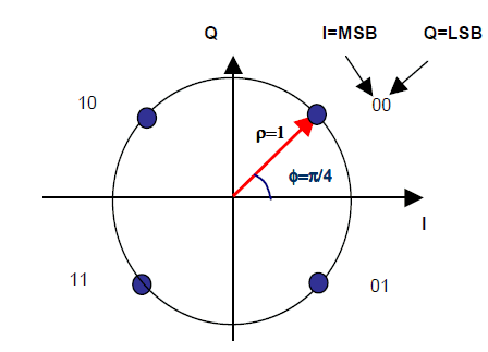
QPSK Constellation
[1] Vogt, Gottfried; , "An analogue polarization follower for measuring the Faraday rotation of satellite signals," Radio and Electronic Engineer , vol.28, no.4, pp.269-278, October 1964