Communication System
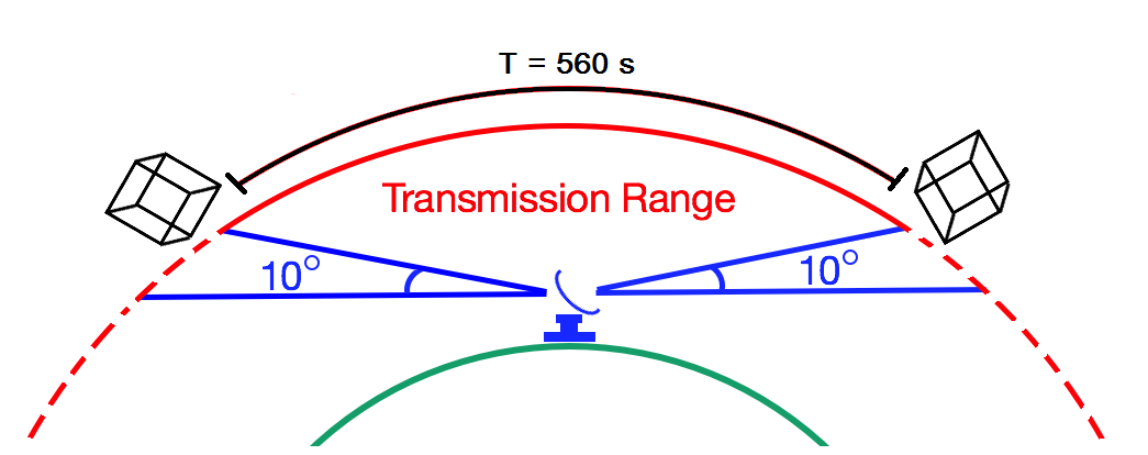
The period of a given satellite is 93.587 minutes, or 5615 seconds. Using the STK10 toolkit, it was determined that the horizon-to-horizon viewing time of a given satellite from an earth station near the poles would be 630 seconds. Antennas that cover the entire viewing angle is unrealistic. Thus, for the sake of communication uplink/downlink times it was decided that the communication channel would only be available within +/- 80°, as illustrated in Figure 1. This leaves approximately 560 seconds of communication time per satellite. It is important to note that using the entire 560 seconds of communication time requires special considerations due to the fact that during a given window, multiple satellites could be in view of the earth stations.
There are two separate communication links used to exchange data between the earth stations and the satellites. The uplink channel is used to communicate the image compression category table to the satellite as well as provide a signal to the satellite for Time Difference of Arrival (TDoA) determination of position. The downlink channel is used to transmit the image data back to the earth stations. The following sections provide a description of each of the communication links, including the satellite and earth station configuration, and provides links to the link budgets for the communication links.
For downlink transmissions, there will be two earth station sites, one in Toolik Alaska and the other in Palmer Station Antarctica. These two sites are optimal because all of the imaging satellites are in polar orbit and will closely cross both the north and south pole. At any given time, there will be 6 imaging satellites transmitting data to the earth station, requiring 6 high gain 5m parabolic dish antennas at each pole to satisfy the high data rate downlink transmissions. These stations will then transfer the coded data to a central server in Atlanta Georgia, where the images will be reconstructed. For the uplink transmission, there will be four earth station sites, all within the Arctic Circle. The four earth station sites, though they send redundant information, are used for TDoA localization. More details on the uplink earth station and the downlink earth station can be found below.
Location and Category Table Uplink
The uplink channel is primarily used to deliver the compression category table to the satellite. This table is very basic, containing a 64-bit integer time value and a single ASCII-byte representing the compression category, separated by a comma. The table will have one line for each picture that the satellite will take, equating to 2807 lines of 10 bytes of data. The uplink earth station will perform calculations to determine what satellites are within the transmission range at a given time. The category table will be sent in a rotating fashion such that each satellite should have a chance to receive their own category table twice during a single 560 second window. Therefore the amount of data destined for an individual satellite during the viewing window is
A data rate of 19,200 bps will be used in order to broadcast this data to the satellites. Since the data rate is lower, which results in the bandwidth being lower, and because multiple carriers are not needed (rotating category tables described above), the uplink channel can be centered at 437.5 MHz in the amateur radio frequency band [1]. This lower frequency has a smaller available channel, but has much better propagation characteristics as compared to higher frequencies. FSK modulation can be used to achieve the 19.2 kbps rate, and results in an occupied bandwidth of 40 kHz when using a 1 kHz deviation. This is based on Carson's Rule:
The signals received by the satellite for the compression category table can be used for geolocation of the satellite based on the TDoA concept. Multiple time synchronized uplink earth stations will transmit identical signals to the satellite. Upon receiving each of the different signals, the controller computer will perform calculations similar to those performed by a GPS receiver to determine the location of the satellite. The computer will calculate pseudoranges for each of the received signals, based on the time delay. Ranging equations will then be used to determine the position of the satellite. This information will then be used by the ADAC system to perform necessary orbit phase corrections.
Satellite Components for Uplink
There are three primary components for the satellite side of the uplink communication link: controller computer, transceiver, and the antenna. The antenna receives the signal from the earth station and passes it to the transceiver. The transceiver performs the analog-to-digital conversion and demodulation and passes the baseband data to the controller computer. The computer then performs the necessary processing to get the compression table into a format for the FPGA to use and to do the TDoA localization calculations.
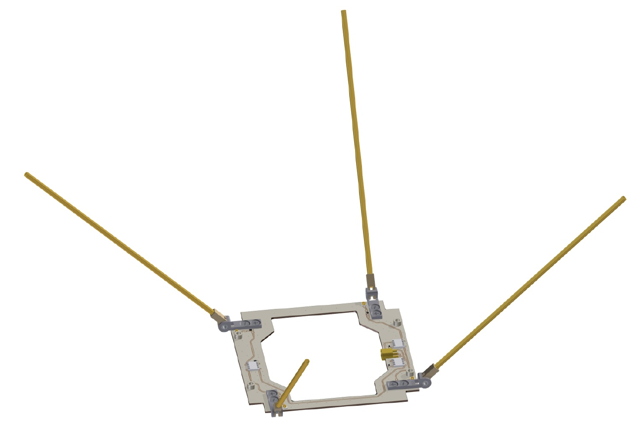
The antenna that will be used on the satellite is a canted turnstyle, as shown in Figure 2, using right hand circular polarization (RHCP). The Rx gain of this antenna is 2 dBi and the beamwidth is approximately 180°[2]. The canted turnstyle is comprised of four monopole antennas, each of length 163 mm (~1/4 wavelength).
The transceiver component will be comprised of the SQTRX-U CubeSat UHF Transceiver from SpaceQuest, Ltd., illustrated in Figure 3. This transceiver is capable of a variety of modulation schemes and data rates up to 19.2 kbps. As described above, the selected modulation is FSK. The SQTRX-U contains an adjustable bandpass filter, an LNA, and connects with the controller computer using a serial UART connection.
Uplink Earth Station Design
Four earth stations are required in order to accurately calculate the location of the satellite in space. All of these earth stations must be in viewing range of the satellite at a given time. Therefore four earth stations within the Arctic Circle will be chosen. The satellite earth stations will be near Toolik, Alaska, Inuvik, Canada, Kiruna, Sweden, and Summit, Greenland.
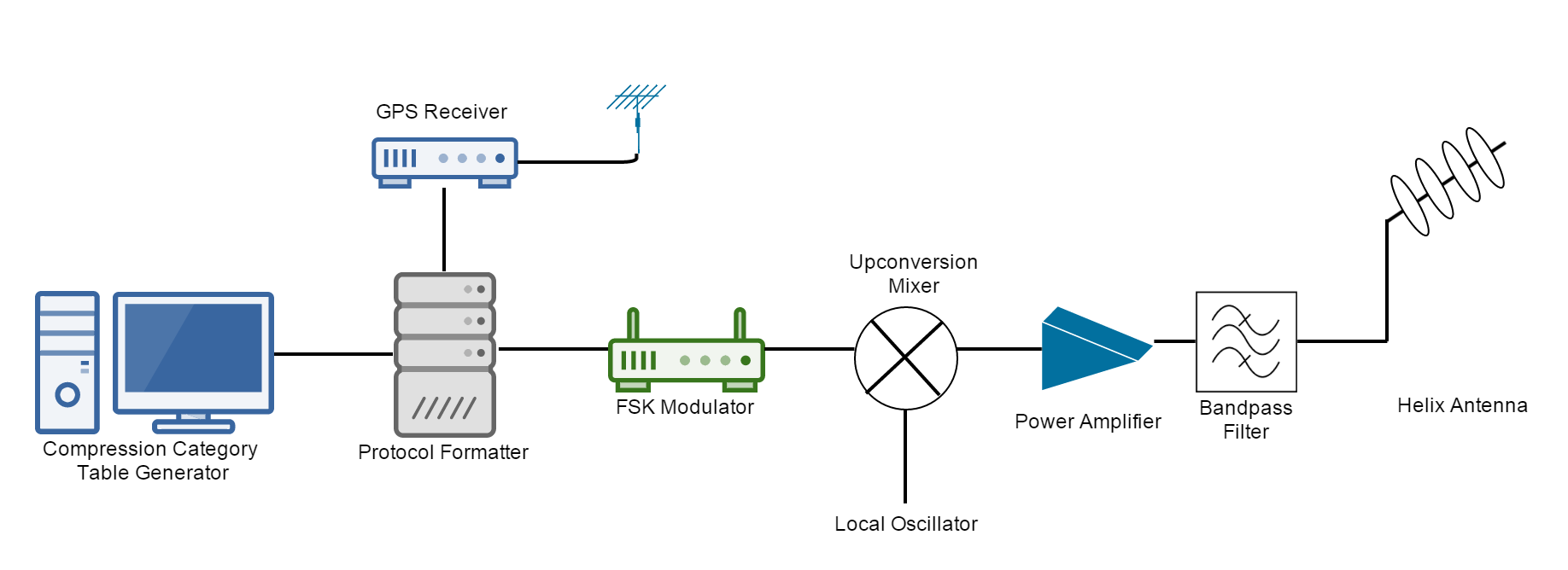
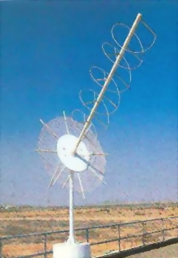
The high level design of each uplink earth station is shown below in Figure 4. The data path starts with the compression category table generation computer system, which uses orbit models to predict where the satellites will be at a given time and set the compression level for that area. This computer system then interfaces with a protocol formatter that generates the necessary digital baseband data to send to the FSK modulator. The protocol formatter takes a GPS signal as input, so that the data transmissions of each of the four earth stations can be synchronized. The output of the FSK modulator is mixed up to the desired frequency of 437.5 MHz and is passed through an RF power amplifier. The output of the amplifier, which is at 10 Watts is passed through a bandpass filter to eliminate spurious emissions and then feeds the helix antenna. The table below provides antenna parameters for the helix antenna based on information from [2], an example of which is shown in Figure 5.
| Parameter | Value |
|---|---|
| Turns | 10.5 |
| Turn Spacing | 1.25 λ |
| Circumference | 1 λ |
| Gain | 16 dbi |
| Beamwidth | 32.2 ° |
| Antenna Length | 1.8 m |
Uplink Link Budget
With the low data rate and long wavelength transmission, the uplink link budget has a large margin of 15.9 dB. More information on the uplink link budget can be found here.
Image Data Downlink
As described on the Imaging System page, approximately 2.05 GB of data needs to be downloaded from each satellite for each orbit. This is a significant amount of data, resulting in the need for a high throughput communication link along with earth stations near both the north and south poles. Considering the 10° buffer for the communication time as described above, only 560 s of transmission time is available to downlink the image data. In order to transmit 2.05 GB of data in 560 s, the throughput of the link must be 31,465,446 bps. However, using an earth station at both ends of the earth, only half this amount (15,732,723 bps) is required.
This is a very demanding requirement and requires significant amount of bandwidth. An X-Band transmitter capable of transmitting up to 50 Mbps was selected for the satellite to meet these requirements. The transceiver supports a variety of data rates and modulation schemes. Based on specification plots for this transceiver, it was determined that a 40 MHz bandwidth QPSK signal using 1/2 Convolutional Coding with constraint length 7 for forward error correction could provide 20 Mbps of throughput.
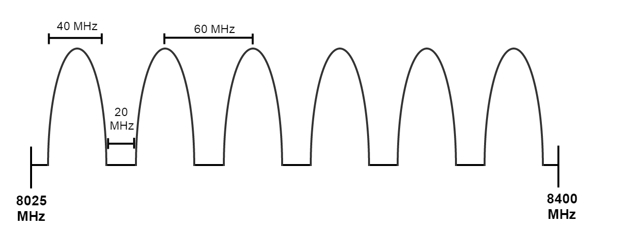
In order to transmit during the entire 560 second viewing window, considerations must be made for the fact that multiple satellites would be transmitting to the earth station at a given time. One advantage of using X-Band is that it provides a larger available bandwidth for CubeSats, allowing for adjacent satellites to use different frequencies. The frequency plan that will be used is shown below in Figure 6. Six different center frequencies will be used, each with a 40 MHz carrier, and 20 MHz separation. The frequency channels will be allocated in a sequential manner and on a rotating basis, such that every sixth satellite uses the same frequency. The following section describes the components used on the satellite for the downlink transmission. This Frequency Division Multiple Access (FDMA) methodology also helps reduce the amount of interference caused at the ground station.
Satellite Components for Downlink
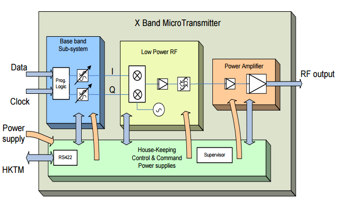
There are two primary components of the downlink communication link on the satellite: the transceiver and the antenna. The transceiver receives digital imagery data from the controller computer system. As illustrated in Figure 7, the transceiver performs the baseband logic, generating I and Q samples for the QPSK modulation, which is performed in the low power RF section. The output of this section is then fed to the power amplifier, which generates a 2 Watt output power that is fed into the antenna. The antenna was selected to be a quadrifilar helix antenna.
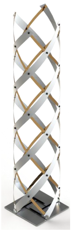
To maximize the amount of data that can be transmitted in a single satellite pass, the satellite’s transmitting antenna beam-width needs to be large enough so that it is able to transmit once the satellite is in view of the ground station (10 degrees off of the horizon). A properly tuned quadrifilar helix antenna has an excellent beam-width and favorable gain for this application. The RHCP quadrifilar antenna to be used will have a beam-width of 140 degrees and gain of 4.0 dBi [2]. When stowed, this antenna will be compressed into a 40x40x15 cm volume. Once the satellite is deployed, the spring loaded antenna will expand into a 40x40x80 cm shape. Figure 8 provides an example of a representative quadrifilar helix antenna
Downlink Link Budget
Due to the high downlink data rate, careful planning was required for the downlink budget. With fine tuning, a downlink link budget with a 2.2 dB margin was obtained. More information on the downlink link budget can be found here.
Downlink Earth Station Design
Transmission of the high resolution images from the satellites will require a downlink with the capacity to handle a high data rate. To accomplish this, two earth station sites will be created, one in Toolik Alaska and the other in Palmer Station Antarctica. Each site will contain 6 high gain (51.7 dBi) 5-meter parabolic antennas, an example of which is shown in Figure 9. With the low power being transmitted from the satellites, these high gain ground station antennas are required to facilitate the large data being transmitted. Likewise, such high gain antennas have a very narrow beam-width allowing the steerable dish antennas to focus on only one satellite without receiving interference from another satellite’s transmission. Once the data has been received at the earth station, it is then sent through SFTP to the main server in Atlanta, Georgia.
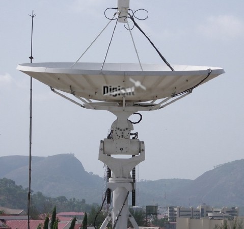
Figure 10 provides a high-level block diagram of the downlink earth station facility. After the signal is received by the high gain parabolic antennas, it is passed through a low noise block converter (LNB) which performs amplification, filtering, and downconversion to an IF frequency around 1 GHz (tunable based on demodulator). The output of the LNB connects to the demodulator, which also performs the decoding of the forward error correction. The baseband data is passed to a computer system which constructs the data into image files. The image files are sent to a central data repository in Atlanta, Georgia, where they are post-processed to remove any redundant data and put the data into a presentable format that can be delivered to customers.

References
[1] Klofas, Bryan, Frequency Allocation for Government-funded CubeSats: NSF Paves the Way, 2011.
[2] King, Jan A., AMSAT/IARU Annotated Link Model System v2.5.3, 2008.
[3] Olson, Gina M., Sergio Pellegrino, Jeremy Banik, Joseph Costantine, Deployable Helical Antennas for CubeSats, American Institute of Aeronautics and Astronautics