ECE 3065: Electromagnetic Applications |
Ryan J Pirkl gtg203a@prism.gatech.edu April 22, 2004 |
| Design Problem | Proposed Solution | Channel Model | Switching Rate | Results & Conclusions | References |
Determining the Maximum Necessary Switching Rate
The train was assumed to be heading in the x-direction at a velocity vtrain = 260 km/h. For this scenario, the dual monopole antennas would then be separated by 2 meters in the y-direction. To model the total field along the antennas’ paths of travel, the field was evaluated at the points (x, 0) and (x, -2). When this data was plotted, it showed the small-scale fading experienced at each of the two receiver antennas. By dividing the independent variable x by the velocity of the train, the small-scale fading as a function of time was determined. The following figures show 100 ms of data for the four cases described earlier.
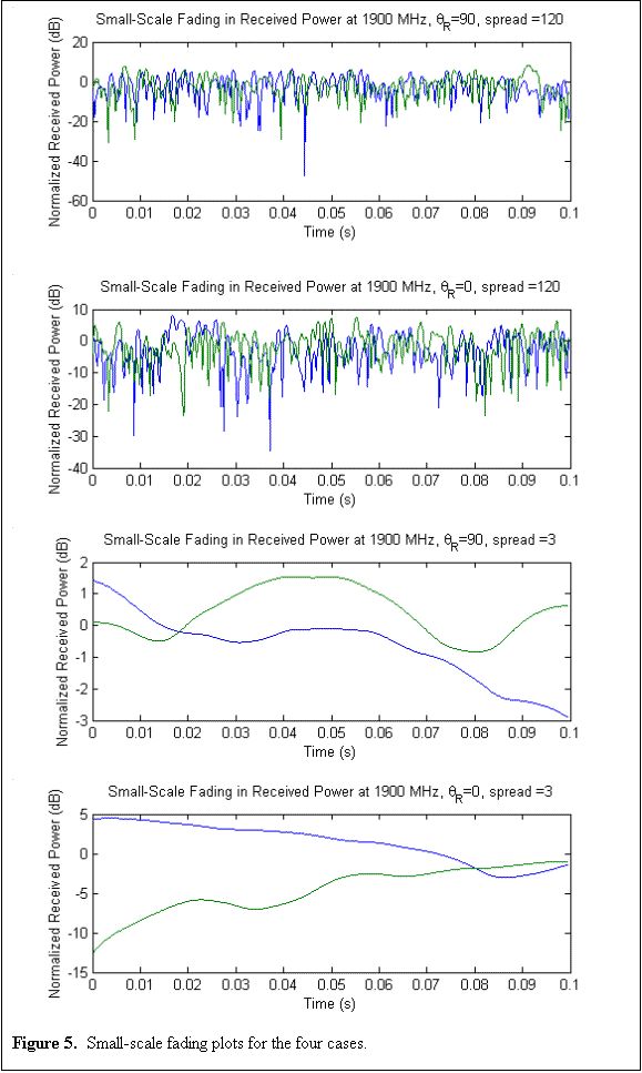 |
To determine the level crossing rates based on this data, the average time intervals between crossings was determined. A histogram of this data is shown in the figure below. Note that the time between crossings is a random variable with a Rayleigh distribution.
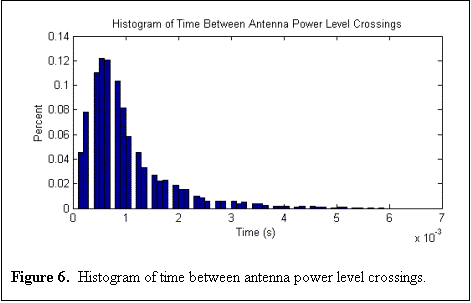 |
By determining the
mean and standard deviation of the data, an approximation for the
actual Rayleigh probability density function ![]() can be formed based on the
equations given below:
can be formed based on the
equations given below:
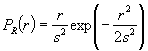 (Eq. 11)
where ![]() and
and ![]() is the mean of the distribution.
is the mean of the distribution.
Converting the Rayleigh distribution from a function of time to a function of Hertz and then integrating results forms a very useful cumulative distribution function. The new plot is a function of frequency and shows the percentage of power level crossing rates for the two antennas that are equal to or less than a given frequency rate.
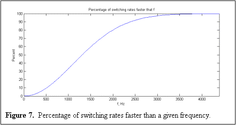 |
According to this
plot, it would require an infinite sampling rate to accurately
monitor which antenna is receiving the strongest signal and
switch to that antenna. However, faster equipment costs
more money, and NTT DoCoMo wants their diversity antenna system
to be as cheap as possible. Therefore, a compromise will
have to be made between switching speed and the effectiveness of
the selection diversity algorithm. According to the plot,
it appears that the best “bang for the buck” occurs
somewhere between 2 and 2.5 kHz. Therefore, the recommended
sampling and switching rate of the receiver is 2.25 kHz, which is
faster than about 85-90% of the power level crossing rates.
Additionally, because this analysis was performed for the
worst-case scenario of small-scale fading where ![]() =90°,
=90°, ![]() = 120°, the sampling and
switching rate will be more than adequate to handle the other
three cases.
= 120°, the sampling and
switching rate will be more than adequate to handle the other
three cases.
| Design Problem | Proposed Solution | Channel Model | Switching Rate | Results & Conclusions | References |