Propagation Model
Documentation
Practicality
References/Appendix
Indoor/Outdoor Propagation Modeling on Georgia Tech Campus
James Armstrong - gtg604k@mail.gatech.edu
Documentation
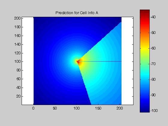
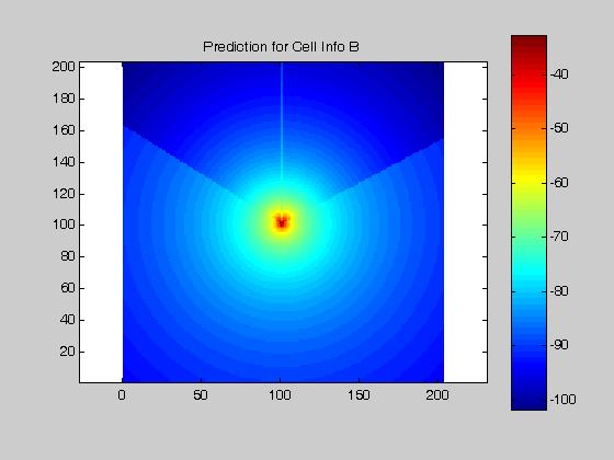
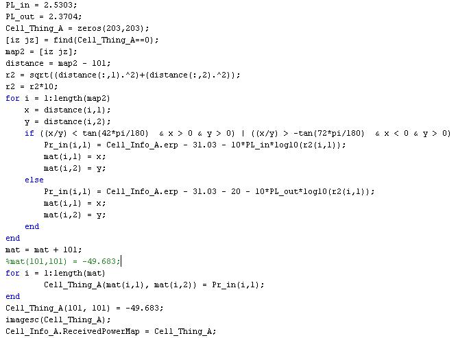
The 4 provided coverage maps were utilized to determine the code that eventually created the received power matrices for maps E, F, G, and H. In order to develop the code used in creating the aforementioned received power matrices, the values from the 4 coverage maps, A, B, C, and D, were used in determining the different path loss values. Upon calculating the path loss values, a test cell was created in order to compare the values to calculate for maps A, B, C, and D, with the actual values. In order to create an entire matrix of received power, the following code was used:
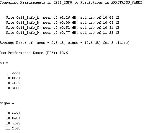
After running this code for all four of the maps, the “CompareMaps” function was used to compare the four created matrices against the originals. The results are listed below:
The maps for the 4 antennas can be viewed below