 |
||||||||||||||||||||||
|
||||||||||||||||||||||
Mars-Earth Communication Link |
||||||||||||||||||||||
|
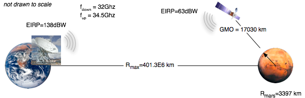
The Mars-Earth communication link is a critical component in the overall network design. Due to the large distance between the Earth and Mars, a reliable link is crucial to ensure good communication. First, the link requirements from the relay satellite to Earth ground station will be determined. Since this design proposes reuse of the antenna for receive and transmit functionality, the link budget will be calculated first for the downlink cases and then those results applied to the uplink case. In the problem statement, the power of the earth transmitter was given as 500,000 Watts with an antenna radius of 34 meters. The goal of these calculations were to determine the satellite and ground terminal parameters to achieve a BER of 1e-6. The basic geometry of the link can be seen in Figure 3. Figure 3: Mars-Earth Down and Up -Link
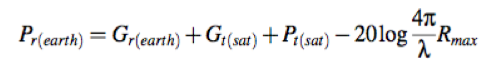
For the downlink calculation, the power and antenna gain of the relay satellite were selected using the link budget analysis. At the specific wavelength for the downlink communication, the gain of the earth station antenna was calculated using (1).
Once the gain for the earth antenna was determined, the link budget shown in (2) was determined by selecting gain and transmit power for satellite.
Since CDMA modulation technique is used for this link, the additional signals act as interferences(Q) and causes added noise to the system. In order to determine the SNR the total noise and interference power was calculated using (3).
From these two expressions and accounting for the processing gain due to CDMA and coding, the BER of the link can be determined for a given SNR is shown in (4).
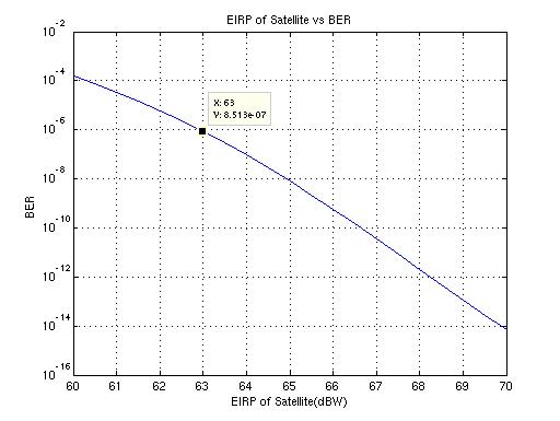
As shown in the plot in figure 4, the EIRP of the satellite can be determined to be approximately 63dBW. Therefore, the satellite antenna gain and the transmit power can be chosen to meet this requirement. A transmitter power of 100Watts with an antenna gain of 43dB yields an SNR of approximately 10.5dB. The beamwidth of this antenna is 1.2 degrees, so the beam will spread to a radius of 4.2e6km by the time it travels to Earth. Also, the efficiency of antenna was assumed to be 0.8 which is nominal for a high-quality antenna. Figure 4: EIRP of Satellite vs BER
However, this analysis is a worst-case scenario where all 50 terminals are communicating at the furthest distance away from the planet. In most situations, the peak power of the transmitter can be reduced and still maintain a quality link. Factors such as earth atmospheric attenuation has not been included in this calculation, so extra link margin is desirable. Since the satellite is sharing its antenna for both transmit and receive. The size of the antenna used for the downlink calculations can be determined from (1) above to be approximately 13cm. From this, a similar link budget expression as in (2) and (3) was used to determine the SNR. Using the frequency for the up-link, the gain of the earth station antenna was calculated to be 81.5dB yielding an EIRP of 138dBW. With the parameters scaled to 34.5Ghz center frequency, the SNR is 16.8dB, with a corresponding BER of 2e-23.
Table 4: Summary for Mars/Earth Link
The calculations for both of these links can be found in the MATLAB file here. The system design (block diagrams and power system) are located in System Design The orbital geometry calculations are located in Spacecraft Orbits |
||||||||||||||||||||||
 (2)
(2)