 |
||||||||||||||||||||||
|
||||||||||||||||||||||
Satellite - Ground Terminal Link |
||||||||||||||||||||||
|
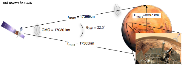
This link allows the ground terminals to communicate to the satellites. The most difficult component of this link is the downlink from the satellite to the ground terminal. In order to cover the entire planet, the antenna 3dB beamwidth (where the gain of the antenna drops by 3dB) should be approximately 22.5 degrees, yield a gain of approximately 18dB. This calculation is made in the MATLAB file located here. The geometry of this link can be seen in figure 5. Figure 5. Satellite - Ground Terminal Link
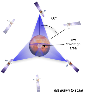
Due to the incident angle of the transmit signal in the polar regions of Mars, there will be a lack of signal coverage in that area. This can best be seen in Figure 6. Figure 6. MARNET Relay Satellite Constellation
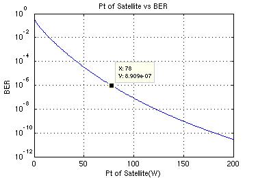
The lack of coverage area can be alleviated by ground relay terminals. Other than this area, the rest of Mars will have service 100% of the time. The first step in evaluating this link is selecting an optimum carrier frequency. To simplify the requirements and calculation, the same carrier frequency will be used for up and downlink communications. Since the antenna gain is fixed, for a given frequency, the radius of the antenna can be determined. To ensure portability, the diameter of the dish should be less than 1m. In addition, there are certain frequency bands which cannot be used since they will interfere with radio telescopes on Earth. Performing these calculations, the optimum carrier frequency was determined to be 1.1Ghz. At this frequency, the diameter of the dish is approximately 0.8m and given the bandwidth of the link, would spread from 850Mhz to 1.3Ghz which is outside the band of any radio telescopes. In order to simplify the design of the the ground terminals a 360 Azimuth dipole antenna will be used. This antenna alleviates the problem of pointing the ground terminal antenna directly at the satellite and allows for fully mobile ground units. Gain for these types of antennas are approximately 2dBi. Since the satellite will be transmitting directly to Mars, the system temperature for the noise calculation will be higher than looking into deep space. The blackbody temperature of Mars (210K) is used as the noise temperature for this link (ref[3]). Using this value, the information from above, and the modulation parameters, link budget equations shown in (1) can be calculated. The transmit power vs BER plot provides the optimum transmit power of 78W to achieve a 1e-6 BER. This chart is shown in figure 7. Figure 7: BER vs Transmit Power for Satellite
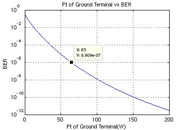
The major difference between this link and the downlink is the system temperature. Since the antenna on the terminals will not be directly pointing at the surface, their system noise temperature should be less than the satellites. This information is not directly known, so through some approximations, it was assumed to be around 175K. Applying the same link budget analysis, the optimum transmit power is shown from the plot in figure 8. Figure 8: BER vs Transmit power for terminal
Since some assumptions were made in this link, some extra margin might be desirable when implementing this system. A transmit power of at least 70dB would provide an extra 5dB margin to ensure a quality link. Therefore, the actual system temperature could be 15 degrees higher and still maintain a quality link. Table 5: Summary for Satellite/Ground Terminal Link
The calculations for these links can be found in the MATLAB file here. The system design (block diagrams and power system) are located in System Design The orbital geometry calculations are located in Spacecraft Orbits |
||||||||||||||||||||||
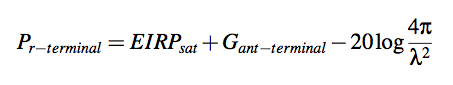 (1)
(1)