Communication systems
Downlinks(from Moon-to-Earth)
We will be using the same carrier frequency fc=24.9GHz (derived from DSN dish specification[6] fmax=32.3GHz and occupied bandwidth by transmit pulse) on all downlinks, use foldable dish antennas with a diameter of 6m and make use of the following building blocks:
Raised cosine pulse shaping filter
We will use a raised-cosine pulse shape filter with a small roll-off
factor α=0.05 (to save bandwidth). The pulse shaping filter will
be implemented as a digital filter with a total pulse duration of 128*Tsys
to accurately approximate the ideal raised-cosine filter.
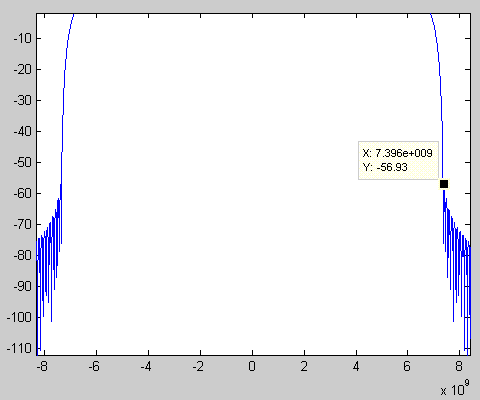
This yields a total occupied bandwidth of 2*7.396GHz=14.792GHz. The
parameters of the filter were optimized using this
MATLAB script in order to satisfy a power limitation for all
out-of-band frequencies of at least -56dB.
The resulting frequency spectrum (at baseband) is shown in the
following figure:

Low noise amplifier (LNA)
We will use a broadband low noise amplifier for the receivers. The block diagrams below show only the principle of operation. In a practical implementation the LNA might be implemented at RF frequency instead of at baseband as in the block diagrams below. We could buy such a broadband LNA from Quinstar Technology. A well-suited LNA would be QLW-00504533-JO (0.1-110GHz, noise figure 5dB) or QLW-18404537 (18-40GHz, noise figure 4.5dB) which can be found here.
High power amplifier (HPA)
For the transmitters we need a broadband high power amplifier that delivers up to 100W of output power. Although Quinstar doesn't currently have such a device we are quite sure that we can contract this company to built it for our project.
Turbo coder and Modulator

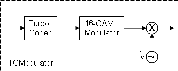
The turbo coder adds redundant bits (rate 3/4) so that error correction can be performed at the receiver. The new bitstream is then fed to a 16-QAM-Modulator that maps the bit sequence into symbols using a raised cosine pulse shaper. The resulting signal is then moved in the RF band by modulating with the carrier frequency.
Demodulator and Turbo decoder

First the signal is moved to baseband and low-pass filtered to remove any unwanted signal components. The 16-QAM demodulator then does the symbol detection and converts the detected symbols into a bit-stream which is then fed to the turbo decoder to perform error correction and output the data bit-sequence.
Transmitter at the lunar radio telescope

The radio spectrum between 1 and 4GHz is sampled with 7bit and fs=6GHz yielding a raw data rate of 42Gbps. This bit stream is then fed to the building block "TCModulator" which adds the turbo coding and modulates the signal using 16-QAM. The resulting signal is then amplified by a high power amplifier (HPA) to yield a transmit power PT of 10W and transmitted using a 5m dish antenna.
Transponder at both relay satellites

First the received signal (using a 5m satellite dish) is amplified using the low noise amplifier (LNA) and then band-pass filtered to get rid of out-of-band noise (and hence increase the SNR). The resulting signal is fed to the building block "TCDemodulator" which demodulates the 16-QAM signal and performs error-correction using a turbo decoder. The output of the turbo decoder is then used as the input bitstream for the building block "TCModulator" which adds turbo coding and modulates the signal using 16-QAM. The signal is then amplified by a high power amplifier (HPA) to yield a transmit power PT of 20W and transmitted using a 5m dish antenna.
Receiver on earth

First the received signal (using a 34m DSN dish) is amplified using the low noise amplifier (LNA) and then band-pass filtered to get rid of out-of-band noise (and hence increase the SNR). The resulting signal is fed to the building block "TCDemodulator" which demodulates the 16-QAM signal and performs error-correction using a turbo decoder. The output of the turbo decoder is then fed to a data processing and storage block that takes care of all further processing.
Uplinks(from Earth-to-Moon)
In order to control the relay-satellites and the lunar radio telescope we need an uplink from Earth to Satellite No.2, to Satellite No.1 and to the moon observatory. Since the required data rate in the uplinks is low we will make use of NASA's DSN employing (a spread-spectrum based) scheme using rate 1/2 turbo-coded QPSK transmission. In order to not disturb the transmission of the spectral data we will use a carrier frequency well below the carrier frequency of the downlinks. The basic operating principle is the same as for the downlinks we just need to replace the 16-QAM-Modulator by a QPSK-Modulator. The uplink channel has been studied for years by NASA and we will make use of this know-how. Hence we will not discuss any link budget calculations etc. further here.