Satellite link design
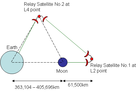
The figure below shows the constellation of earth, moon and the two relay satellites in order to get a better understanding the distances between all the involved entities:

Identification of links
In total there are three links (Moon - Satellite1, Satellite1-Satellite2 and Satellite2 - Earth) that need to be considered.
Perfect alignment assumption
Actually the relay satellite no.1 needs to orbit around the L2 point as
discussed here. This makes steering of the transmit dish on the moon
and the receiver dish of satellite no.2 necessary. However for the
following we assume that both satellites remain fixed at their
respective locations and that the dishes are perfectly aligned.
For the reception of the signal on earth we make use of NASA's Deep
Space Network (DSN)
that provides us with three large receive
antennas
located in the US, Spain and Australia.
Atmospheric Effects
The link from Satellite2 to earth is the only one where we have to deal with atmospheric effects (such as rain attenuation) since the two others are space links.
Identification of free parameters
Since we have the freedom to choose operating frequencies, transmit
power and satellite dish antenna sizes (the dish sizes on earth are
given since we use the DSN) we encouter a lot of free parameters.
From basic considerations we know that increasing the carrier frequency
gives us a benefit in antenna gain for a given dish size. However at
the same time the path loss increases also.
Choice of modulation scheme
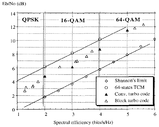
Before calculating the actual link budget we need to determine the type of modulation we want to use. [4] provides a comparison of different modulation schemes with turbo code error correction and discusses the required SNR for BER of 10-5 and the spectral efficiency of the different modulation schemes in the following figure:

Since each modulation scheme requires a different bandwidth to transmit
a certain bit rate we need to calculate the actual required SNR in
order to be able to compare the different modulation schemes:
relative SNR = required SNR + relative increase in noise power (with
respect to
a reference modulation scheme) - reference SNR
We picked the following modulation schemes as examples:
| Modulation | spectral efficiency | required SNR from figure | relative required SNR for specified bitrate |
| QPSK | 1 bit/s/Hz | 2.00dB | 0.77dB |
| 16-QAM | 2 bit/s/Hz | 4.75dB | 0.56dB |
| 16-QAM | 3 bit/s/Hz | 6.00 dB | 0.00dB |
| 64-QAM | 4 bit/s/Hz | 8.75dB | 1.55dB |
| 64-QAM | 5 bit/s/Hz | 11.5dB | 3.28dB |
We took 16-QAM with conv. turbo code at 3bits/s/Hz as a reference and
obtain the values in the last column. These values can be interpreted
as follows:
For QPSK with 1bit/s/Hz we would need 0.77dB more transmit power or
antenna gain in order to compensate for the increased noise power due
to increased transmission bandwidth. Likewise for 64-QAM with 4bit/s/Hz
we would need 1.55dB additional
transmit power or antenna gain. This shows that 16-QAM with 3bit/s/Hz
is the optimal transmission
scheme. Using 16-QAM with 3bit/s/Hz spectral efficiency means that we
will use 14GHz bandwidth to transmit our 42Gbps signal and use a
convolutional turbo code with rate 3/4.
Although the actual occupied bandwidth is larger (see here) the effective bandwidth (for SNR
calculations) is equal to 14GHz.
Link budget calculation
Taking the required SNR Eb/N0 = 6dB we can derive the required carrier-to-noise ratio
C/N = Eb/N0 +10*log10(fb / BW)
where fb = 4bit*14GHz and BW = 14GHz. This yields a required C/N = 12dB which we need to obtain at all receivers.
We created an Excel spreadsheet to
calculate link budgets for all three
links at different frequencies and account for rain attenuation (data taken from [1] for the DSN complex located in the US) for the
Satellite2-earth link.
We used the following values in our link budget calculation:
| Parameter | Value |
| Speed of light c | 299,792,458 m/s |
| Boltzmann constant k | 1.3806505E-23 |
| Length of link1 l1 | 61,500,000 m |
| Length of link2 l2 | 439,683,750 m |
| Length of link3 l3 | 405,696,000 m |
| Diameter D of all comm. dishes (except DSN) | 5m |
| Efficiency of all dish antennas | 0.9 |
| Diameter D of earth receiver dish (DSN) | 34m |
| Modulation scheme | 16-QAM with rate 3/4 turbo code |
| Effective Bandwidth | 14 GHz |
| Carrier frequency | 24.9GHz |
| System temperature Tsys for sat. receivers | 30K |
| System temperature Tsys for earth receiver | 16.2K |
| Transmit power PT for moon transmitter | 3dBW = 2W |
| Transmit power PT for sat1 transmitter | 20dBW = 100W |
| Transmit power PT for sat2 transmitter | 5dBW = 3W |
| Rain att. (sat2-earth): Region | Region E (Mojave Desert) |
| Rain att. (sat2-earth): exceedence rate | 0.01% |
| Rain att. (sat2-earth): Rain rate | 22mm/h |
| Rain att. (sat2-earth): effective rain-length | 2,000m |
From our link budget calculations (including rain attenuation (0.01% exceedence) on the link from Sat.2 to Earth) we get the following results:
| Link | Transmit power PT | Received power PR | SNR |
| Moon-Sat1 | 3dBW | -99.5..-94dBW | 12.8..18.3dB |
| Sat1-Sat2 | 20dBW | -99.6..-94.1dBW | 12.7..18.2dB |
| Sat2-Earth | 5dBW | -102..-101.2dBW | 13.1..14dB |
From these results we can make the following conclusions:
- Since we are using a very large bandwidth, attenuation and gains differ and hence we encouter different receive SNRs for different parts of the RF spectrum. In a practical implementation we would need to use an equalizer to compensate for this effect. For simplicity we will omit this device in the discussion of the communication systems.
- The link from Sat1-Sat2 is the most "difficult" one since it has the lowest received SNR (due to longest distance). Our approach works includes a design reserve of 0.7dB.
- Transmit powers have been minimized to just yield enough receive SNR
- Because attenuation and gains differ for different parts of the RF spectrum we could split our data signal into sub-bands and send them sperately to achieve a higher data rate (since we can send at a higher data rate if we have enough receive SNR for a particular subband) For example we could use OFDM to achieve this.
Up to now we have not taken into account the additional noise due to amplifier noise. The broadband low noise amplifier we want to use has a noise figure of 4.5dB which is pretty high. This leads to a decrease of receive SNRs which would mean that we either need to increase the transmit power or user larger dish antennas if we use this amplifier.