antennas
NASA’s Deep Space Network
The Deep Space Network (DSN) is an international network of large steerable reflector antennas supporting most interplanetary spacecraft missions. In addition to communications, the DSN uses these antennas for radio and radar astronomy observations to explore the planets, the galaxy and the universe. The DSN employs very large steerable antennas, cryogenic low noise amplifiers, multi KW transmitters, powerful modulation & coding techniques and minimal-loss digital processors to maximize the telemetry and command data. The downlink Telemetry and Tracking processor minimize processing losses by using sub-Hz tracking loops, multi-bit sampling, and matched filtering. The DSN consists of three communications facilities placed approximately 120 degrees apart around the world: in California's Mojave Desert at Goldstone; near Madrid, Spain; and near Canberra, Australia. Each facility has several antennas ranging from 15m to 70m in diameter. The strategic placement permits constant observation of spacecraft as the Earth rotates.
For our project we will utilize the 34 m High efficiency (HEF) antenna. The 34 m HEF antenna has a mount which is of azimuth-elevation type and it operates in both axes at 0.40 degrees/second. The reflector is precision shaped for maximum signal gathering capability. For X-band frequencies the G/T of the 34 m DSN is about 45 dB/K.
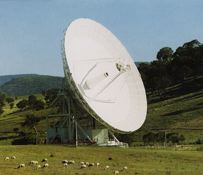
34 meter High Efficiency (HEF) DSN antenna
Phased Array Antenna
For our project, we require an antenna which needs to transmit at very high data rate. We also require an antenna whose directivity can be configured electronically. Phased array technology offers significant benefits over mechanically pointed parabolic antennas, including the elimination of deployable structures, moving parts, and the torque disturbances that moving antennas impart to the spacecraft. They also have added advantages in terms of scanning, reconfigurability. The latter feature results in the conservation of spacecraft power and enables the ability to take precision optical measurements while simultaneously transmitting high-rate data. Phased-array antennas contain a multitude of radiating elements, typically arranged in a rectangular or triangular tessellation. Beams are formed by electrically adjusting the relative phase of the radiating elements using ferrite or semiconductor devices.
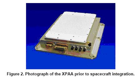
The X band phased array [6] that we are going to use combines the functions of antenna, 2-axis gimbal, gimbal controller, and solid-state power amplifier (SSPA) in a single, low-cost package. The division of the SSPA function into 64 individual element amplifiers enhances the reliability and fault tolerance of the X-band downlink system.
The antenna operates at a frequency of 8225 MHz, and can transmit data at maximum of 105 Mbps with a minimum effective isotropic radiated power (EIRP) of 22 dBW. It has an integral controller and power conditioner, communicates with the spacecraft over a fiber-optic data bus, and is fully space qualified. The antenna aperture consists of an 8 x 8 array of modules, each comprising a dielectrically loaded, 2 circular waveguide, two orthogonal antenna feeds, a phase shifter, and a dual power amplifier. These modules are encompassed in a single 12 x 13 x 2.9-inch enclosure with a total mass of 5.5 kg. The antenna has a maximum scan angle of 60 degrees over all azimuth angles.
Quadrifilar Helix X-Band Antenna
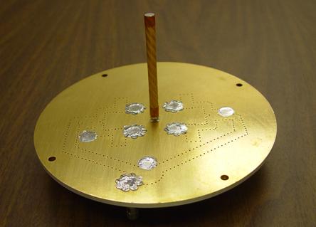
This antenna [7] is a very low mass, space qualified antenna that operates in X-band frequencies. These antennas are capable of supporting very high data rates and upto 10 W of tranmsitted power. It has a nominal 3 dB gain, but it weighs less than 250 gms. Such type of antenna are ideally suited to be installed on our Lander.