modulation
QPSK Modulation
There are different modulation schemes that can be used to modulate the data:- namely BPSK, QPSK, m-QAM, FSK etc. In space communication power is severely limited. FSK is not generally used as it would require very high bandwidth to modulate our data resulting in very low bandwidth efficiency. Higher constellation QAM also can’t be used in our case as that would require very high C/N ratio. The choice is between QPSK and BPSK. The advantage of BPSK is that it requires the lowest C/N ratio. The drawback is that the data rate achieved using BPSK is very low. QPSK is basically two BPSK links operating on the same radio channel with their carriers in phase quadrature. Therefore the BER of a QPSK remains the same as BPSK. At the same time the data rate is doubled. The only penalty we pay is in terms of C/N ratio. QPSK requires 3 dB more C/N ratio than BPSK. Our project demands high data rate without losing much on bandwidth and power. Because of these tradeoffs we decided on using QPSK modulation scheme for the raw data received from the rover.
The following block diagram shows a simplified QPSK modulator and demodulator.
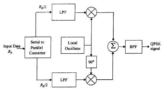
Fig. QPSK Modulator Block Diagram
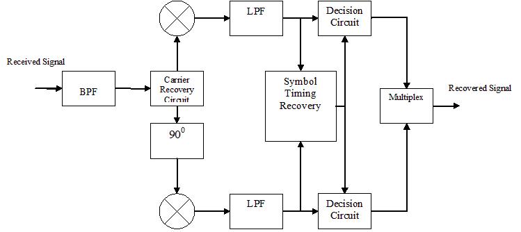
Fig. QPSK DEmodulator Block Diagram
Pulse shaping
When rectangular pulses are passed through bandlimited channel, the pulses will spread in time and the pulse for each symbol will smear into the time intervals of succeeding symbols. This will cause intersymbol interference. In our case, the data coming from the rover is modulated over a 8.225 GHz carrier before it is transmitted to one of the DSN. The receiver at the DSN demodulates the RF signal to recover the baseband signal. ISI will occur at the receiver due to band limiting of the modulated waveform unless filters satisfying Nyquist criterion are used. Therefore spectral shaping is done at the transmitter so that the out of band signals are brought to a low level.
We will use a root raised cosine filter with a rolloff factor of α = 0.6. The roll-off factor gives the excess bandwidth. This filter will be a bandpass filter centered at the carrier frequency Fc = 8.225 GHz. The RRC filter will limit the bandwidth of the transmitted baseband signal to Bocc = Rs*(1+α), where Bocc is the occupied bandwidth. And Rs is the symbol rate.
Raw Data Rate = 7.5 Mbps. By using rate 2/3 turbo code, Bit rate = 11.25 Mbps
Using QPSK modulation Symbol rate Rs = 5.625 Msps
Bocc = 5.625 Msps * (1+0.6) = 9 MHz
At the receiver the RRC filter will limit the noise that reaches the receiver output to a noise Bandwidth of Bn = Rs Hz.
The occupied bandwidth defines the RF spectrum required to transmit all of the signal energy. Hence the Channel Bandwidth = 9 MHz.
The figure below shows the amplitude response of the raised cosine filter with different roll-off factors as well as the impulse response of the raised cosine filter. As can be seen from the amplitude response, by increasing the roll-off factor Beta the time domain ripple decreases. This means the pulse will die down quickly. Therefore the excess bandwidth can be reduced at the expense of elongated impulse response. This directly effects on the number of taps required for the filter. Larger the number of taps larger is the delay in the filter output.
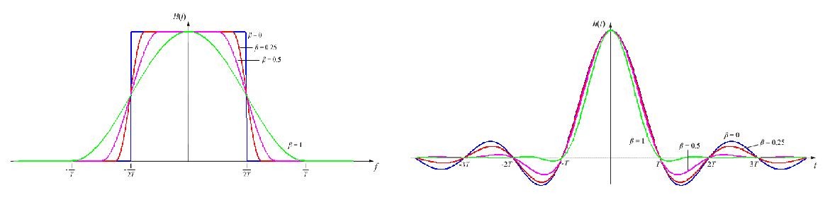
Fig. Amplitude Response of RRC Filter FIg. Impulse response of RRC Filter
Spectral Usage
| Link | fc | Bandwidth |
| Rover to Lander | 405 MHz | 9 MHz |
| Lander to Rover | 450 MHz | 57.6 kHz |
| Lander to Earth | 8.225 GHz | 9 MHz |
| Earth to Lander | 8.425 GHz | 76.8 kHz |
RF Hardware
Regenerative transponders are used to provide constant output power regardless of uplink attenuation. We planned our link budget such that the C/N ratio at the Lander is above the threshold of the onboard processing demodulator.
Below is the regenerative transponder inside of the lander, which receives a UHF signal and transmits it in X-band.
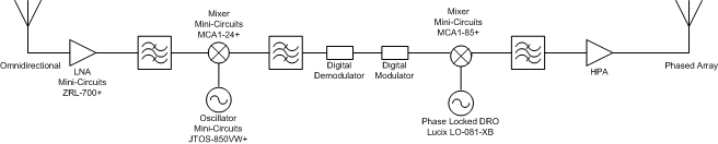
Links to data sheets for components used are shown below. The Lucix parts are available in space-certified form. The Mini-Circuits parts are not space-certified, but provide a reference point for specifications of similar parts that could be space-rated.
| Component | Manufacturer | Part Number | Link |
| Low-Noise Amplifier | Mini-Circuits | ZRL-700+ | http://www.minicircuits.com/pdfs/ZRL-700+.pdf |
| Mixer | Mini-Circuits | MCA1-24+ | http://www.minicircuits.com/pdfs/MCA1-24+.pdf |
| Oscillator | Mini-Circuits | JTOS-850VW+ | http://www.minicircuits.com/pdfs/JTOS-850VW.pdf |
| Mixer | Mini-Circuits | MCA1-85+ | http://www.minicircuits.com/pdfs/MCA1-85+.pdf |
| Oscillator | Lucix | LO-081-XB | http://www.lucix.com/dro16.html |
Below a UHF transmitter, this same basic circuit is used in both the lander and the rover.
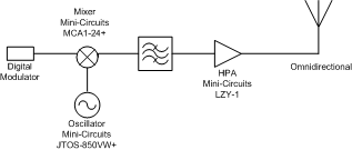
| Manufacturer | Part Number | Link |
| Mini-Circuits | MCA1-24+ | http://www.minicircuits.com/pdfs/MCA1-24+.pdf |
| Mini-Circuits | JTOS-850VW+ | http://www.minicircuits.com/pdfs/JTOS-850VW.pdf |
| Mini-Circuits | LZY-1 | http://www.minicircuits.com/pdfs/LZY-1.pdf |
Below is the X-band receiver, used in the lander. The output of this could either issue a command to the lander or a command to the rover which would then be transmitted using the UHF transmitter.
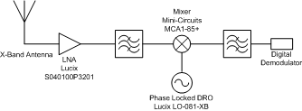
| Component | Manufacturer | Part Number | Link |
| Low-Noise Amplifier | Lucix | S040100P3201 | http://www.lucix.com/amps10.html |
| Mixer | Mini-Circuits | MCA1-85+ | http://www.minicircuits.com/pdfs/MCA1-85+.pdf |
| Oscillator | Lucix | LO-081-XB | http://www.lucix.com/dro16.html |