Communication between Moon Base Station and Earth
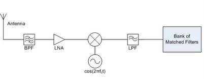
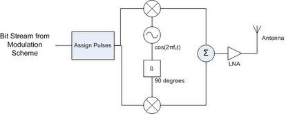
The basic block diagrams for the RF transmitter and receiver are shown below. These components are used for the base station on the moon, earth station and for the rover. Although different elements will have differing uplink and downlink frequencies, their basic structure is the same.
Transmitter:
Receiver:
Because our modulation scheme uses no quadrature modulation, it was unnecessary to use a phase shifter. The low noise amplifier is essential in order to minimize the amount of noise in the system. On the receiver, the band pass filter is the first component in order to minimize the harmonics amplified by the system.
Communication between Moon Base Station and Rover
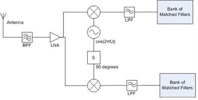
This communication network is performed via QPSK, a simpler modulation scheme but with few bit errors, especially over a short distance. The transmitter and receiver for QPSK modulation are shown below.
Transmitter:
Receiver:
In both the transmitter and reciever, the in-phase portion of the signal is on the top and the quadrature portion is on the bottom. This modulation scheme allows 2 bits per symbol. In this transmitter and reciever, we will use a 90 degree phase shifter.
The matched filters used in the receivers here, are the optimal linear filter that maximize signal to noise ratio (SNR) in the presence of additive stochastic noise. A matched filter is obtained by correlating a known signal, or template, with an unknown signal to detect the presence of the template in the unknown signal.The impulse response of the matched filter is given by
where h is the filter, Rv is the covariance matrix of noise and s is the desired signal.
.


