Experiment Considerations and Plan
Background:
From the preliminary results discussed in the literature review of W band DAVID and WAVE missions and our own rain attenuation simulations shown in the “Atmospheric Attenuation data” section in the V band experiment, it is clear that there is a wide range of possible attenuation which could be severe at times. As a result, we need to have good fade mitigation techniques to counteract and still communicate reliably. Fade mitigation can be done using either uplink/downlink power control, adaptive transmission or site diversity. In this work, we propose to use adaptive transmission via changing coding and modulation to be able to cope with such fade fluctuations. This can be performed in three main ways: hierarchical coding, hierarchical modulation and data rate reduction as discussed in [1]. Hierarchical coding changes the coding rate based on the channel conditions while hierarchical modulation changes the modulation scheme. Data rate reduction schemes tune the data rate based on the channel conditions and are usually not able to provide as much gain as the other two adaptive techniques [1].
Proposed modulation/coding schemes:
We propose to use a combined scheme of hierarchical coding and modulation where the coding rate and modulation are adapted based on the channel conditions. Table 1 shows the specific details of each of the modes we propose to be in depending on the channel behavior. As can be seen, variable rate turbo codes will be used in conjunction with BPSK, QPSK and 8-PSK modulation schemes.
Table 1. Different modes of adaptive coding and modulation proposed
Rationale for choices:
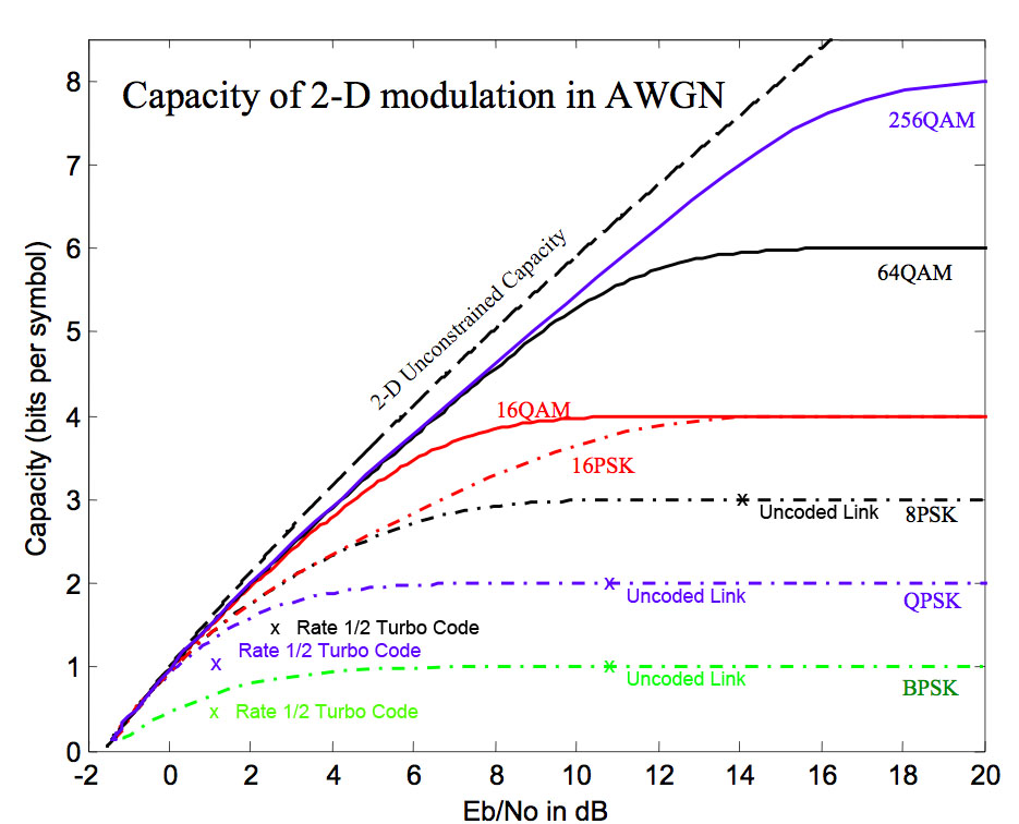
Turbo codes are chosen owing to their efficiency in improving system capacity as close as possible to the Shannon limit, more so than any other codes available at this time [1]. This kind of robust coding gives us additional gain that will help compensate for the high rain attenuation that is possible, as can be seen from the “Atmospheric Attenuation data” section in the V band experiment. Further, the chance to vary the turbo coding rate in four levels gives a lot of flexibility to perform experiments. Figure 1, below, shows typical coding gain for a rate 1/2 turbo code for the modulation schemes that will be used [3].

Figure 1. Eb/No for Uncoded Link vs. Rate 1/2 Turbo Code [3].
The same rationale applies to the choice of modulation techniques. For instance, when the channel conditions are very poor, a BPSK modulation scheme with a 1/4 turbo code could be used to maintain the required SNR that maintains at least 10 Mbps. When there is very little attenuation in the channel (clear day), an 8-PSK modulation scheme with 5/6 Turbo code may suffice. From our analysis of the link budgets for the W-band, we found that coding gain is very much necessary owing to the high path losses experienced. Hence, it was decided not to provide an uncoded modulation scheme.
Adaptation criteria and algorithm development:
We propose to use set BER thresholds that are experimentally determined to switch between the turbo coding rates and modulation schemes. Similar to the approach used by Rossi et al for the V-Band [2], we propose to set some initial BER thresholds by using the simulations. But our approach is slightly modified as it keeps checking that the target data rate is sustained.
As design parameters, we fix bandwidth and a target BER of 10-6. Using Eb/No vs. W/Rb curves that can be drawn using digital communication theory and simulations for each of these coding/modulation combinations, we can choose the Eb/No that can sustain the W/Rb (with Rb at least 10 Mbps) at the target BER. If the target BER is not reached, the system will to switch to a lower modulation scheme and/or higher coding gain. On the other hand, if BER is better than the threshold, then it is an indication that we can get a higher data rate using a higher modulation scheme like 8-PSK with a higher coding rate. Initially, we propose to perform such calculations offline and set exact BER thresholds of when to change between the different modes listed in Table 1. However, while the system can be initially run using these, experimental confirmation and optimization of the thresholds is necessary to ensure good performance for the real channel.
Proposed Experiment plan:
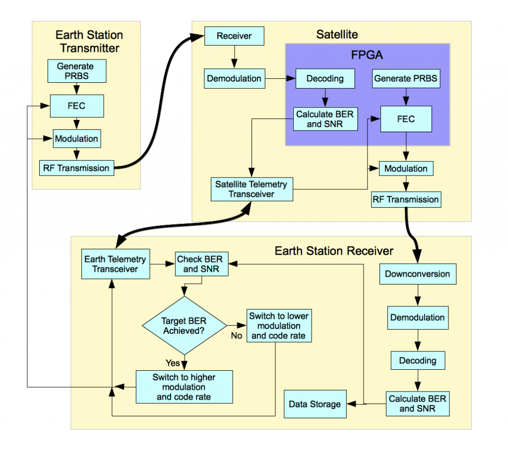
Figure 2. Flow chart showing the experiment procedure.
The sequence of the experiment steps are illustrated in the flow chart shown in Figure 2. First, a reference pseudo random sequence is generated at the transmitter which is common to both the satellite and the Earth station. A 1/4 rate Turbo code is then applied followed by BPSK modulation and transmission over the link. The receiver performs the necessary down conversion and demodulation as described in the Transponder section. This is then followed by calculation of BER in the FPGA by comparison with the reference pseudo random sequence. The SNR and the BER are relayed back to the Earth station through the satellite’s telemetry link at a lower frequency. Based on the received SNR and BER values, the receiver checks if the target BER is reached. If conditions are good, the system will switch to more bandwidth efficient modulation and coding to attempt to increase data rate. Information about the modulation and coding rate are synchronized between the earth station and satellite transmitters and receivers.
References:
[1]A. D. Panagopoulos, P. M. Arapoglou and P. G. Cottis, “Satellite Communications at Ku, Ka and V bands: Propagation impairments and mitigation techniques,” IEEE Communications Surveys and Tutorials, 2004, Vol. 6, No.3.
[2] T. Rossi, E. Cianca, M. Lucente, M. De Sanctis, C. Stallo, M. Ruggieri, A. Paraboni, A. Vernucci, L. Zuliani, L. Bruca and G. Codispoti,”Experimental Italian Q/V Band Satellite Network,” IEEE Aerospace Conference, 2009.
[3] M. Valenti and R. Seshadri. Topic: “Turbo and LDPC Codes: Implementation, Simulation, and Standardization.” West Virginia University, Morgantown, WV. http://wireless.vt.edu/symposium/tutorials/2006/Valenti.pdf, Jun. 7, 2006.


