W Band Uplink & Downlink Budgets
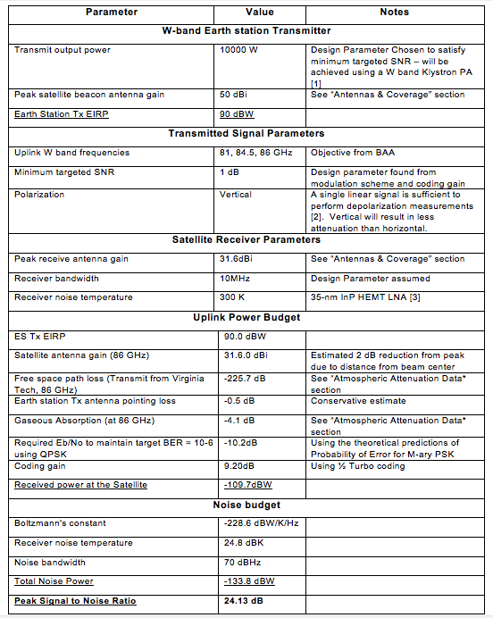
The link margins for the uplink and downlink are based on the SNR required at the receiver to achieve communication with a low BER (below 10^-6). The challenges in designing this link (as compared to links at lower frequencies) include high atmospheric loss, extremely high rain attenuation, and limited antenna gain on the satellite (due to footprint requirements). Another challenge is the limited output power of lightweight power amplifiers such as Traveling Wave Tube Amplifiers (TWTA). Working within these constraints, it is possible to achieve a clear day link margin of only 4.13dB for the uplink and -0.42dB for the downlink using just TWTA technology and room temperature receivers. To achieve a higher link margin it is necessary to use better but more costly technology at the earth stations. A Klystron at the earth station will be used to transmit at 10 kW power [1]. With these parameters, the clear day link margin is 24.13 dB. Based on this link margin, estimated availability of the link can be calculated, shown in Table 1, below, and the uplink and downlink budgets are shown in tables 2 and 3, respectively.
Table 1. Estimated Link Availability
The downlink transmit power is limited by the amplifier technology which can be put onboard the satellite and by the power available from the satellite. For the downlink to have a positive clear day link margin, cryogenically cooled receivers are required at the earth stations to lower the noise temperature to 36 K [3]. While these technologies are not practical for mobile or consumer broadcast applications, they are commonly used in deep space links and will be useful to enable the team to study the link under less than ideal conditions. To further improve the downlink, compact klystrons for space-borne applications with peak power up to 2000 W may be available [6], and trade studies will be conducted during Phase 1 to determine the best downlink amplifier technology.
Table 2. Uplink clear day link Budget for the W-band at 86 GHz
Table 3. Downlink clear day link budget for the W- Band at 71 GHz
References:
[1] R. J. Trew, “High-Frequency Solid-State Electronic Devices,” IEEE Transactions on Electron Devices, vol. 52, no. 5, pp. 638-649, May 2005.
[2] R. Acosta, J. Nessel, R. Simons, M. Zemba, J. Morse, and J. Budginer, “W/V-Band RF Propagation Experiment Design,” 18th Ka and Broadband Communication Conference, Ottawa, Canada, Sept 2012.
[3] L. Samoska, S. Church, K. Cleary, A. K. Fung, T. Gaier, P. Kangaslahti, R. Lai, J. Lau, X. B. Mei, M. M. Sieth, R. Reeves, and P. Voll, “Cryogenic MMIC low noise amplifiers for W-band and beyond,” in Proc. 22nd International Symposium on Space Terahertz Technology, Tucson, AZ, April 2011.
[4] N. R. Robbins, D. R. Dibb, W. L. Menninger, Z. Xiaoling, D. E. Lewis, “Space qualified, 75-Watt V-band helix TWTA,” IEEE Vacuum Electronics Conference (IVEC),pp.349-350, April 2012.
[5] M. Valenti and R. Seshadri. Topic: “Turbo and LDPC Codes: Implementation, Simulation, and Standardization.” West Virginia University, Morgantown, WV. http://wireless.vt.edu/symposium/tutorials/2006/Valenti.pdf, Jun. 7, 2006.
[6] B. Steer et. al. “Extended Interaction Klystron Technology at Millimeter and Sub-Millimeter Wavelengths.” Communications & Power Industries Canada Inc., Ontario, Canada, Jun. 2007.


