 |
|

| |
|
|
|
|
|
|
Verge/Lander System Requirements Verge
*Note: all electronic components will have radiation-testing services performed by Space Micro, Inc (SMI). Not all components may be able to be engineered and tested by SMI and therefore, we will utilize SMI’s excellent quality-of-service to help select cost-efficient radiation-hardened device vendors for those few components. Due to cost reasons, space-hardening15. Due to constraints in cost, space-hardening will be limited to those electronics that absolutely need it. For more information about SMI’s space-materials solutions, see [16]. Rover
Quick Overview of Structure The Verge lander primarily consists of:
Other minor components on the lander include:
Lander Design EOSystems is pioneering new methods of spacecraft project management and construction. The main engineering challenges are a consequence of the lander’s mass and size. A consequence of the low mass and small size is that we have to design the whole thing as a single entity. All of this spacecraft’s functionality is integrated, where the mass requirements, size requirements, and functionality drive its design. The lander structure is boxy in shape and unfurls its legs after launch. Due to mass constraints, the lander is light but simultaneously strong, consisting of carbon-based graphite-fiber. This material makes it lighter than aluminum and more rigid than steel. Titanium fittings are glued and fitted onto the beams to bolt them together. The rover is held inside the lander by bolts and special nuts, which are released after landing using special small explosives. Lander Sequence of Events
Landing After landing, the lander will alter the high-gain antenna position for maximum signal strength, deploy the photovoltaic panels to the programmed surface configuration, and await commands from EOSystems. The following are the planned steps to be taken, upon landing:
As part of the Google Lunar X Prize, requirements specify that spacecraft must collect digital data (still camera images) and transmit it to Earth. Altogether, this mooncast consists of1:
Additionally, the spacecraft will be required to send a Mooncast detailing its arrival on the lunar surface, and a second Mooncast that provides imagery and video of the journey roaming the lunar surface. The Mooncasts will represent approximately 1 gigabyte of stunning content returned to the Earth. Camera Characteristics The Verge camera, a commercial-off-the-shelf version, will provide high-resolution images, video, as well as (as a last resort) navigation capabilities. The camera provides two core functionalities:
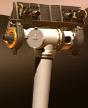
Onboard processing can be used to track objects real-time and that information, when combined with the camera’s navigation system, will also provide course correction in transit to the Moon. Verge Mast Assembly Similar in placement to the Sprit and Opportunity rovers (launched in the Mars Exploration Rover mission), the panoramic Verge imager is mounted on top of the lander’s pop-up mast, to provide the best panoramic view during descent on the Moon and while landed, shown below. This mast assembly is capable of 360º rotation for panoramic operation2. The imager has an elevation of 1.5 m above the lunar surface with which to take images. One motor for the mast assembly camera is in the horizontal plane. A separate elevation motor can point the pancam 90º above the horizon and 90º below the horizon.
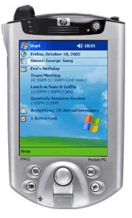
The computer, and all electronics, will be assured to be shock-resistant, due to various stages of launch and transit that may place a slight burden on these devices. The computer system selected by EOSystems engineers, the HP iPAQ Pocket PC h5550, shown below, is stored in a temperature-controlled shell onboard the lander. The iPAQ provides ideal performance with its ability to synchronize and share data while in space, during transit to the Moon, while orbiting the Moon (when facing Earth), and once landed. Additionally, as expected, this HP iPAQ PDA is a solid-state device with no moving parts, meaning it is more shock-resilient than other computers. Additional benefits include cost ($700 newly purchased, excluding space-hardening) and the 400-MHz Intel XScale Technology-Based Processor, which specifically focuses on accelerating multimedia and security. The iPAQ also allows stores critical information using non-volatile memory. The iPAQ protects stored data from being erased if a battery discharge or full reset occurs. It offers up to 17 MB of storage space, 128 MB of SDRAM (to store flight software, engineering, science, images, and rover information), and 48 MB of Flash ROM (to store flight software and time-critical data). Additionally, with the compact flash expansion slot, as much as 16 GB of collected video, imagery, and data can be collected and stored17. As stated in the communications section, if there is not a line-of-sight transmission possible to the ATA, the raw signal will be stored on lander. Therefore, this additional memory will prove useful. For more specifications about the iPAQ h5550 or additional secure digital flash memory, please see two tables below.
Other Considerations Other computer systems considered include the commercially-available IBM RAD6000 computer, which is radiation-hardened to survive space flight. Due to added expense (after space-hardening, believed to be between $200,000 and $300,000), slower processing speed (clock rate of 33 MHz, 20 million instructions per second), and the substantially lower 6 MB non-volatile memory, this solution was not pursued further. Other costly solutions were provided by General Dynamics. Visit their website for more information regarding space computing. Capabilities In addition to serving as the brain of the lander, the central computer will consult a synchronized system clock to determine when data transmission is possible. Additionally, preprogrammable functions include a search-mode to reacquire Earth if no command is received after 3 hours and preprogrammed attitude maneuvers at superior conjunctions. Lander's Hewlett Packard iPAQ Pocket PC H5550 specifications17:
Verge's Expandable Flash Memory Component specifications18:
Verge Attitude and Orbit Control Attitude control is the control of the orientation of a spacecraft. Controlling the lander’s attitude, in transit to the Moon, requires measuring attitude using numerous sensors. Changing attitude (to re-orient lander to the desired attitude) requires actuators9. Verge’s orientation in space must be stabilized and controlled so that its high-gain antenna may be accurately pointed to Earth, so that the heating and cooling effects of sunlight and shadow may be used intelligently for thermal control, and so that propulsive maneuvers may be executed in the right direction. Images gathered by the Verge Imager (VI) will also be integrated as a starfield sensor (to provide sensor redundancy) and to take images of the Moon during low lunar orbit. These images will be compared to recorded data from the Clementine and Lunar Prospector orbiters for position-determination. Attitude Subsystem: Litton LN-200 Inertial Measurement Unit (IMU) The attitude-determining mechanism used by the Verge lander is the space-rated version of the commercially-available Litton LN-200 IMU, which contains a gyroscopic attitude-measurement mechanism and a solid-state silicon accelerometer attitude-changing mechanism. IMUs utilize their gyros and accelerometers to compute 3-axis position and velocity information, from a given starting position9. The Verge lander will be fully stabilized in three axes. The LN-200, specifically, consists of three fiber-optic gyroscopes (one for each axis of spacecraft rotation), three micromachined silicon accelerometers, and a microprocessor. This unit senses acceleration and rotation about a three-axis perpendicular plane and outputs temperature-compensated angles and velocities through an RS-485 digital output to the main computer9. The three fiber-optic gyroscopes provide a frame of reference against which spacecraft rotation can be measured10. Because gyros are subject to drift, EOSystems is also considering the use of infrared earth/lunar horizon sensors. Using horizon sensors allows Verge to accurately determine pitch and roll measurements and the gyroscopic-measuring tool compliments this toolkit to measure yaw information. Additionally, horizon sensors provide the added benefit of determining attitude information on the dark sides of the Earth and the Moon. Significant features of the Litton LN-200 include low cost (uses highly reliable industrial parts and advanced technology), fiber-optic gyroscopes (simple product with low-parts count), highly reliable (solid-state, no moving parts), conduction cooling (no additional external cooling necessary), and small size/weight and low power (see Table 1)12. As part of the initial design process, star trackers were initially considered as a potential attitude-determining component but, due to their high sensitivity (especially from sunlight reflected from thruster gas), they are no longer being considered. In addition to Litton LN-200 to determine attitude information, additional redundancy is in place to ensure “smooth sailing.” Two sun sensors, which were also used on NASA’s Surveyor missions in the late 1960s, allow the spacecraft to orient itself using the Sun. Verge uses these sun sensors initially to determine its orientation after separating from the launcher upper stage. The sun sensors can also be used to re-orient the lander if it accidentally goes into an uncontrolled spin, to provide more reliable attitude information11.
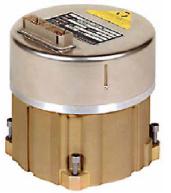
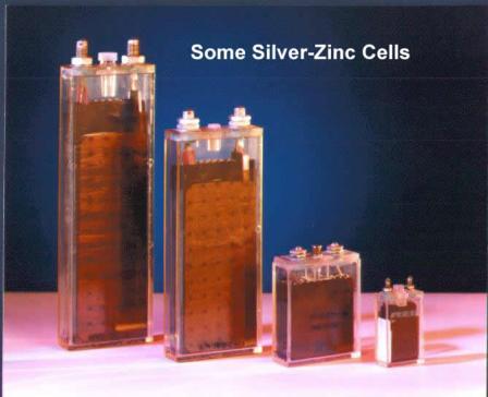
Attitude Adjustment Subsystem (AAS) Verge will use attitude knowledge provided by the Litton LN-200 IMU, horizon sensors, and ground commands to control lander spin-rate, attitude, and maneuvers. It is necessary for Verge to spin at a specific rate, nominally stated as 5 rpm, as a passive thermal control technique. A considerable operation of AAS is the periodic precession-maneuvering for correct interception of the Moon target, with respect to the spin axis. This is necessary because the attitude of the lander will shift from what it is projected to be. Attitude adjustments will be provided by a commercial-off-the-shelf product using catalytic-decomposition reaction thrusters (using monopropellant hydrogen peroxide and a hydrocarbon fuel). Attitude adjustment allows the lander/rover to stay on correct course and provides it the ability to maneuver into a feet-first configuration during the landing sequence. Lander power is provided by a combination of solar panels and a batteries, due to the fact that the lander will be designed to survive the lunar night. Therefore, the lander power will use the solar panels for normal power usage and batteries for emergency/lunar night power usage. Solar Panels Due to the lack of an atmosphere to diffuse sunlight, solar panels on the Moon produce more power than they would on Earth, which results in further weight savings since smaller panels can be used. On Earth, 6% of incoming solar energy is reflected through the air and 16% is absorbed by the air. Clouds are not included in those figures. Hence, on a clear day a solar panel on Earth receives 22% less power than one in space, or on the Moon. On cloudy days, this number is even higher30. Electrical power is partially provided by the spacecraft's solar panels. They are mounted on the lander’s body and take effect shortly after the payload-housing has been jettisoned. The panels themselves are an off-the-shelf technology, provided by Spectrolab, Inc28. Spectrolab was selected to provide power due to its efficient single junction GaAs solar panels, with a power density of 228 W/m2. Additionally, with a mass density of 1.61 kg/m2, the total mass contributed by the solar panels is 1.61 kg. A total of 1 m2 of solar panels will be attached to the exterior of the lander and will require a maximum of 150 W of power during flight and while on the Moon. Distribution of power will be controlled through digital interface of the onboard HP computer. In the case that solar panels are inoperable (for whatever reason), power will efficiently be distributed from the silver-zinc batteries. Batteries Because the lander and rover will “sleep” during the lunar night, batteries will be needed to perform minimal tasks (routine, non-high bandwidth transmission to Earth stations). Therefore, in addition to solar panels, lander power will be provided by silver-zinc rechargeable batteries. These batteries were selected because they contain more energy-density than lithium-ion batteries and require less space. Additionally, using the solar panels, these batteries are able to be recharged, which would be necessary following the lunar night. The silver-zinc batteries would likely be provided by Yardney Technical Products, shown below, which has had numerous space-applications of these types of batteries38. Nominally, a 60 Watt-hour (maximum) battery would be sufficient for the core tasks during the lunar night, since only the primary tasks of transmitting/receiving and computing would be necessary. The silver-zinc batteries will also be used as a backup source of power, in case the solar panels are obstructed from direct view of the Sun energy source. The computer would not be transmitting continuously in “sleep-mode” and therefore would only require a small amount of power.
Temperature Control The temperature of the lander may nominally vary anywhere between Heating The electronics box, housing the most space-sensitive devices, will be kept between 10°C and 20°C, during the lunar night, using thermal blankets. Only those instruments that require thermal insulation will be placed in this electronics box. Competitively-priced, off-the-shelf thermal protection solutions will be provided by General Dynamics (Thermal Products Center), which offers Multi-Layer Insulation thermal blankets31. Cooling The solar panels, as purchased from Spectrolab, will be made from composite materials that can withstand the wide temperature variations of space without significant deformation. To avoid excess heating, primarily due to solar radiation, the lander will consist of composite material that will efficiently dissipate this heat as necessary. This includes Spacemicro’s HiREC™ temperature-sensitive paint which assures no degradation up to 750°C32. [1] http://www.googlelunarxprize.org/lunar/competition/guidelines
|
|||||||||||||||||||||||||||||||||||||||||||||||||||