 |
|

| |
|
|
|
|
|
|
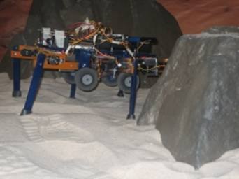
Rover Overview The main objectives of the mission can be summarized as putting a rover on the surface of the Moon to acquire high definition (HD) videos and navigate in search of evidence of previous lunar missions. This rover must be both simple and efficient. Its main constraints are its mass, available payload constraints on physical dimensions, power consumption, and cost. The first consideration when designing the rover is how it travels on the Moon’s surface. The classical solution is to simply use wheels and model it as a modern vehicle. Recently, the Georgia Tech Human’s Lab designed a robot for spatial application which makes use of legs in addition to wheels for obstacle avoidance. The name coined for this robot comes from the designer, Byron Johns, and is “ByRobot” (videos).
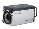
Its legs are useful to explore unfriendly terrain, such as a thick layer of moon dust. It also provides a greater height from the ground to clear large obstacles. EOSystems engineers considered numerous advantages to use the ByRobot, which led the rover architecture to be based off it. The ByRobot cannot be used as it is currently designed because the dimensions are too small. It must be scaled to be large enough to pass obstacles, yet small enough to avoid becoming wedged between two rocks. Other considerations while scaling include physical constraints in the lander, weight, and power consumption. The rover will have to be able to move autonomously, in case the link with Earth is lost, and also to reduce the cost of communications. Thus, the next part of the design to consider is the command system. Classically, when rovers are faced with a difficult situation, they will stop and wait for instructions from Earth. In order to be autonomous, EOSystems engineers must design the rover to make decisions. Therefore, it must gather information about its lunar environment. Eight infrared sensors, two on each side, will be integrated to locate obstacles around the rover. These sensors are the first step to autonomy but will not be sufficient on their own. The obstacles must then be analyzed in order to decide which path is optimal. This task will be assisted by the use of two stereo cameras providing a 3D image of the environment. EOSystems engineers will process these images with shape recognition software to determine if the rover can continue without danger. By coupling these devices’ information, the rover can avoid most obstacles, but there must be some redundancy within the system for the cases when the rover makes the wrong decision or simply when a decision cannot be found. Many issues caused by the relief cannot be avoided; however, an inclination sensor will detect variations in slope of the path followed by the rover to help prevent disaster. This is an inexpensive, compact device, so our engineers have integrated multiple sensors for more accuracy. Moreover, this sensor will assist in guiding the rover. There are several solutions available for guiding the rover. The first is tracking from Earth via USN. This solution is accurate but very expensive and slow. Another solution is the use of three distant antennas using time delay, frequency delay, and phase shifts to locate the rover. However, the antennas must be in three different locations to minimize the dilution of precision, and their positions must be known very accurately. Thus, this solution is not realistic even if our budget could support it. Another option is to use a gyroscopic inertial measurement unit, which would give the position of the rover relative to the position of the lander. These devices are very expensive and do not provide much accuracy. The price of the solutions proposed above leads to reflect on other cost effective solutions even if the accuracy is diminished. Recently, some space agencies used a “digital solar aspect sensor” to determine the azimuth and elevation of the sunrays received. These angles can be corrected using the inclination sensor. An odometer can then be used to approximate the position of the rover relative to the lander. The odometer will also be useful to prove to Google Corporation that the rover followed a 500 m path (or more!). To win the Google Lunar X Prize, a few criteria have to be satisfied. One of them is the acquisition and transmission of HD videos and images. More precisely, high definition panoramic photographs, high definition videos and self portraits of the rover must be captured. In order to satisfy these requirements, a HD camera will be embedded on the rover. Its functionality will support both videos and images. Among the cameras available, the HDC-X300, manufactured by Sony, is well adapted with high quality, low weight and low power consumption and, therefore, fulfills our requirements. This camera will be paired with a real time data compressor to reduce the data rate to an acceptable value to transmit to Earth. This is further explained in the Communications section of our site.
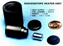
Finally, in order to acquire panoramic views and for more liberty in data acquisition, a camera boom will be utilized to rotate the camera. The arms currently available have the same price and weight range, only differing by the rotation axes. The Garcia G6 manufactured by Acroname Robotics satisfies our requirements.  Now that data acquisition is assured, a communication system has to be designed to transmit data to earth and to receive commands. The rover must send data back to Earth; however, it is not possible to send it directly via a high gain directional antenna because an alignment of this antenna with the receiver on Earth would be very difficult. Thus, an omni-directional antenna must be used, but this provides a new set of problems. Our solution is to transmit the data through the lander, which can support more power and a high gain directional antenna. Indeed, it would necessitate transmitting data from the rover to the lander through an omni-directional antenna and then transmitting to Earth via a high gain antenna. The antenna is chosen depending on the frequency of data transmission. The omni-directional antenna selected for use on the rover is a dipolar antenna, HGV-2404U, manufactured by Hyperlink Tech. It has an interesting gain of 4 dBi and fits well with the working frequency chosen for communications between the rover and the lander. For tracking purposes and redundancy in case the lander communication systems fail, a transceiver is implemented on the rover. This will be the identical one used on the lander and will communicate with USN, if needed. The transmitter consumes around 35 W, thus, will be turned off when not needed. However, the receiving part only consumes 8 W and can be used to send commands directly to the rover. EOSystems engineers have decided to keep it active permanently. For more information about the communication with the lander and Earth, you can see the video stream section of our site. Once all devices on the rover are built, they need to be coordinated. This function is assured by a microcontroller. The major problem of microcontrollers used in space is that old technologies are typically used for more reliability limiting the speed of operations. However, AMI Semiconductors, Inc. recently produced fast, low-power microchips. These chips consume less than 15 mW and are over twice as fast as today’s generation. They can be used in microcontrollers and are radiation resistant, optimal for use in space. This provides our engineers a faster decision making process. As previously explained, the robot must be a perfect size for travelling to and traversing on the Moon. EOSystems engineers have decided upon a rover with 25cm wheels to go through minor obstacles with 70cm x 70cm dimensions (length x width). The height is determined by the components added and will be around 70cm as well. The legs of the rover will be moved using two servomotors each, and the wheels will be independently motorized to allow rotations and to avoid sinking. There are two solutions considered for supplying power. The first and most popular is the use of solar-cells. These are efficient, but heavy and need solar exposition. The other solution is more expensive and makes use of Radioisotope Heater Units (RHU), which employ radioactivity to provide power. These units are light weight and work independently from environmental conditions. Moreover, these units can provide heat, which is useful for surviving the lunar night. Therefore, EOSystems engineers have decided to use the RHUs with a combination of solar panels, to reduce cost, in order to win the bonus prize for a lunar night survival. An RHU weighs 1.4oz (1 in * 1.3 in) and provides 1 W which is very efficient in comparison with the solar cells. The rover will require approximately 250 W for its entire system.
Space exploration requires being able to face many harsh environmental conditions not found on Earth. Due to this, many devices are not specified to work in some of these intense conditions. Therefore, the internal temperature of the rover must be maintained in a determined range in order for the components to work properly. This can be achieved by using the RHU’s heat production. We will make use of multiple temperature sensors to regulate it. In addition, the electronic components must be resistant to electromagnetic perturbations which could alter data. Some parts used are “space ready,” but others will require another solution. Most components (except the antenna) will be held in an electromagnetically “bullet proof” box, avoiding perturbations due to environmental conditions such as electromagnetic storm, sun rays, etc. [1] http://en.wikipedia.org/wiki/Radioisotope_heater_unit
|
||||||||||||||||||||||||||||||||||