 |
|

| |
|
|
|
|
|
|
Orbital Mechanics It is essential to have knowledge of orbital mechanics to understand space operations as it holds a cornerstone value in orbital path design. Orbital mechanics is the study of the motion of planetary objects, artificial satellites, and space vehicles. This field deals with trajectories of space bodies, their orbital changes, and interplanetary transfers. In this section, we will study the orbital mechanics that have been designed for our rocket to lift off from Earth and carry a payload to the Moon. In this section, we will shed light on various planetary laws and fundamental principles dealing with space flight mechanics. Before delving into the specifics of our mission’s orbital mechanics design, two great individuals who have played a pivotal role in shaping astronomy must be mentioned. The German astronomer, Johannes Kepler (1571 – 1630), shown below, developed the three laws of planetary motion using the previous analysis and observations of the Hungarian astronomer Tycho Brahe. These laws hold a fundamental value in the study of orbital mechanics as they define the motion of a body in an ellipse. We employ his laws when determining the flight path duration from our parking orbit to the moon.
Sir Isaac Newton, shown below, requires no introduction.
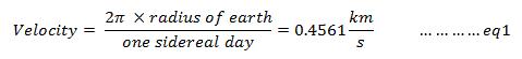
“Of all the mathematics developed up until the time of Isaac Newton, Newton’s was by far the better half.” -- Lifelong rival of Isaac Newton, Gottfried Wilhelm von Leibniz4 The roots of modern day orbital mechanics can be traced to Newton in the early 17th century, when he formulated the laws of motion and universal gravitation5. Newton realized that the force by which an apple falls from a tree to the ground is the same one that makes planets fall around the sun6. Newton also concluded such a planetary orbit should be elliptical after he was able to deduce Kepler’s laws while solving his own equations for laws of motion and universal gravitation. Newton’s laws are employed in various parts of our design solution. Selecting a rocket launch location determines the inclination and altitude of the orbit. The most propellant-efficient orbit for a given altitude and payload mass is one that has low inclination. As such, the launch site needs to be as close to the equator as possible. Inclination is the angular distance of the orbital plane of a launched vehicle from the plane of reference, which is usually the primary body’s equator (the Earth in this case), and is measured in degrees. Inclination of 0 degrees means that the plane of the orbiting body is the same as the equatorial plane of the planet and is in the direction of rotation of the planet. We have selected the Reagan Test Site on Omelek Island, located 2,500 miles southwest from Hawaii (9°2.890'N, 167°44.585'E) due to the Island’s close proximity to the equator. Omelek Island is part of the Kwajalein Atoll in the Marshall Islands2. Earth rotates about its axis towards the east. We can determine the rotational velocity of the earth at the equator to be:
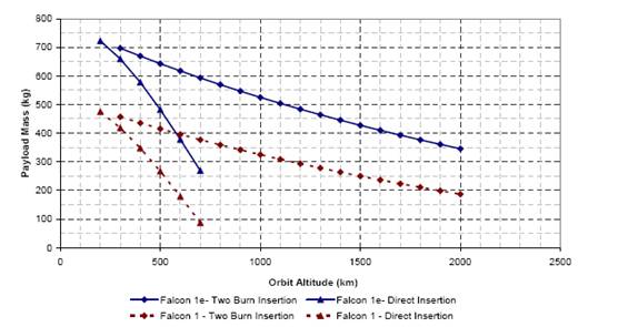
As such, any easterly launch near the equator will have a velocity increment of approximately 0.4561 km/s imparted due to Earth’s rotation3. On the other hand, a launch which is not into an equatorial orbit will reduce the payload capabilities of the rocket and this reduction has a linear relationship to inclination5. Launching the Spacecraft into Orbit During launch, the rocket engine is ignited, tremendous thrust is produced, and the spacecraft is lifted and accelerated to orbital velocity. This initial liftoff flight is concluded at the 2nd stage burnout of the rocket engine. From there onwards, the spacecraft is in free flight. The figure below shows the data provided by the SpaceX Corporation regarding launches from the Reagan Test site2. We have estimated our payload mass at launch to be 600 kg. As can be seen from the figure below, Falcon 1e with such a payload mass can reach an altitude of approximately 700km when employing a two burn insertion.
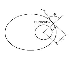
Three primary variables r (distance from the center of the earth), v (velocity of the vehicle), and Φ (angle between the velocity and position vector) are needed to specify the vehicle’s orbit.
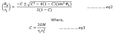
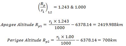
Let r1, v1, and Φ1 be the initial launch values. Then, the following equation allows us to solve for the perigee and apogee altitudes.
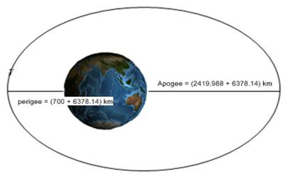
G is the universal gravitational constant, and M is the mass of Earth. Equation 2 results in two solutions. The smaller of the two results will be the perigee value and the other will be the apogee value of the parking orbit. Our spacecraft’s launch will terminate (ideally) at perigee with a Φ1 value of 90°. In addition, we will accelerate our vehicle to a velocity of 7.9 km/s at this location. As such: r1 = (6378.14 + 700) x 1000 = 7,078,140 m v1 = 7900 m/s G = 6.673 x 10⁻¹¹ m3kg-1s-2 M = 5.9742 x 1024 kg Putting these values in equation 2 yields:
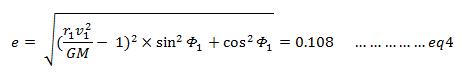
The perigee result was expected to be 700km based on an ideal Φ1 value of 90°. However, we expect Φ1 to have a value close, but not equal, to the ideal. We plan to use the Reaction Control System (RCS) mentioned in the propulsion system design section to counter errors in our trajectory. We can also calculate the eccentricity of this elliptical orbit using the following equation4.
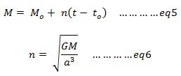
Position Location in Parking Orbit It is paramount to track the spacecraft while in parking orbit. This is important because transfer orbit processes must be initiated at the right time and at the desired apogee location of the orbit. In this section, a few equations will be developed that will help locate the position of the spacecraft in the orbit after a specific period, as well as finding the time duration required to travel to a certain position. To do this, the mean anomaly, M, must be introduced5. Mean anomaly of an orbiting body is a measure of the angle it will move about the center of its orbit relative to its perigee location. This simplifies measuring the time of flight between two locations on the orbit as it changes linearly with time10.
where Mo is the mean anomaly at time to, n is the spacecraft’s average angular velocity, and a is the orbit’s semi-major axis. Equation 5 can provide a perfect solution for a circular orbit. However, since our orbit is elliptical, the radius varies. As such, eccentric anomaly, E, must be defined. This value is related to the mean anomaly by equation 7.
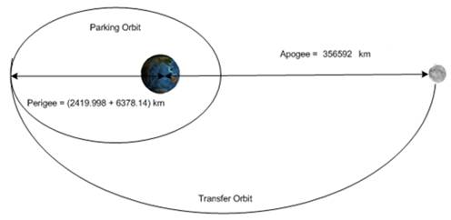
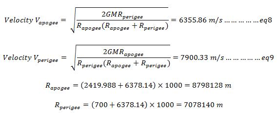
With the help of equation 5, 6 and 7, the position of the spacecraft at any time t in its orbit can be determined. The next stage of the journey to the Moon requires a transfer from parking orbit to transfer orbit. This is accomplished by firing the spacecraft’s engine when it reaches its apogee. The goal is to make the apogee of the parking orbit serve as the perigee of the mission orbit. The apogee of the transfer orbit corresponds to the Moon.
Using equations 8 and 9, the velocity of the spacecraft can be determined both at the perigee and apogee of the parking orbit. The velocity at apogee and perigee is given by:
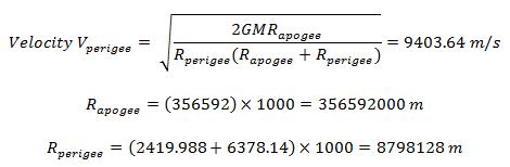
The result also confirms the perigee velocity of 7.9 km/s used in earlier calculations. The velocity that will be required at the perigee of the transfer orbit to obtain the required apogee is now calculated. Again employing equation 9:
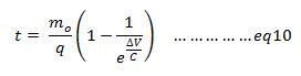
As such, a velocity increment of (9403.64 – 6355.86) = 3047.78 m/s is required. To achieve this velocity increment, the spacecraft will burn its engine for a time period t. This burn period can be calculated using equation 10:
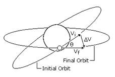
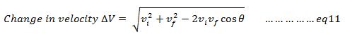
where mo is the initial mass of the spacecraft, q is the rate of ejection of mass flow, and ΔV is the change in velocity. Our mission is to initiate the engine burners at time to such that the spacecraft reaches its transfer orbit perigee point after a time period t. Using equations 5, 6, 7, and 10, the correct initial time to and the location of the spacecraft in its orbit can easily be calculated. A crucial flight maneuver in our mission is to adjust the orbital inclination. The Moon’s orbital inclination with respect to Earth’s equator varies between 18.29° to 28.58°. Vehicle launch from the Reagan Test Site provides an orbital inclination of 9.1°2. As such, in order to change the spacecraft’s orbital plane inclination, a change in the direction of its velocity vector is required, shown below. This is achieved by having a component of Δv perpendicular to the initial velocity vector vi. A fuel efficient way is to have the inclination change during the tangential burn will be employed at the apogee as part of the transfer orbit5, preventing the fuel consumption of a separate plane change process. Equation 11 is used to calculate the necessary velocity change requirement.
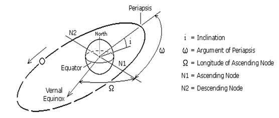
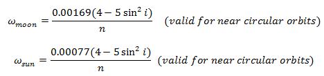
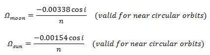
where vi is the initial velocity, vf is the final velocity, and θ is the change in the inclination angle required. Most of the equations developed in the preceding sections assume an ideal situation where the spacecraft’s calculated orbital path is not perturbed by any force other than the rocket’s thrust and Earth’s gravitation. However, this is generally not the case. Our spacecraft will be tracked during its journey to the Moon as mentioned in the TT&C section. The aforementioned RCS systems will be employed during this flight phase to bring the spacecraft back on track in case of a change in trajectory. A few causes of perturbations are mentioned in this section. However, there are many more, such as perturbations due to Earth’s oblateness, atmospheric drag during launch, etc. Perturbations caused by gravitational forces of Sun and Moon One of the main causes of perturbation to the orbit is the effect of the Sun’s and Moon’s gravitation. They cause perturbations in longitude of the ascending node and argument of perigee.
Perturbations caused at the argument of perigee5:
Perturbations caused at the longitude of ascending node5:
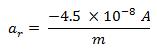
where i is the inclination of the orbit, n is the number of times the orbit will revolve per day, and Ω and ω are in degrees. Perturbations caused by solar radiation Solar radiation cause changes in all of the orbital mechanics parameters of the spacecraft by imparting acceleration. The magnitude of this acceleration is provided by:
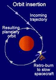
Where ar is the imparted acceleration, A is the cross-section area exposed to the sun, and m is the mass of the spacecraft. Lunar orbit insertion (LOI) is by far the most critical step of the spacecraft’s journey to Moon. The process is to place the spacecraft in the lunar orbit at the correct position and time. In addition to precise time and position, the spacecraft needs to be decelerated in a controlled manner. The deceleration is achieved using the retrograde burners on board the spacecraft.
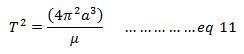
This is a complex maneuver. If the engines burn too long, the spacecraft’s speed will reduce to the point that it drops onto the lunar surface instead of being captured by the orbit. On the other hand, if the engines do not burn long enough, the spacecraft will pass the Moon into an unpredictable and uncontrollable elliptical orbit13. Our system is designed to use the Moon's gravity to trigger the pre-programmed commands to initiate the retrograde burners at the correct time and position during its flight. This will reduce the velocity and place the spacecraft in a 90km x 100km orbit around the moon, similar to the Luna 21 orbit mission14. The spacecraft will be captured into the lunar orbit once this retro-burn process is accomplished. Launch window is a period during which a launch must be initiated to meet mission objectives. The window depends on the location of the earth and moon in their respective orbits. The launch time must be selected carefully so that the orbits of the Moon and spacecraft overlap at the calculated intersection time. Furthermore, since Earth rotates 5° every 20 minutes, the time of the day to launch a spacecraft must be chosen cautiously in relation to the direction towards the desired perigee12. The Moon will have a perigee distance of 356,592 km on January 30, 2010, at 9:00 Universal time (UTC). The corresponding local time at Reagan Test Site will be 9:00 PM. We plan to intercept the moon at this time to reduce the travel distance of our spacecraft. In case of bad weather or any other unforeseen technical delays, our next launch window will depend of an expected intercept date of February 27th, 2010, at 21:41 (UTC). The Moon’s distance from earth will be 357,831 km on this date8. Our goal is to insert the spacecraft into parking orbit around Earth during which time its telemetry components will be analyzed to determine if the systems are functioning properly. This will establish how well the spacecraft survived the initial launch operation. Any system not functioning properly will perform pre-defined tests to restore proper functioning or further analyze the problem. Communication through USN will also be tested to confirm reliable data transfer and signal strength6. The spacecraft will remain in the parking orbit for two complete orbital revolutions before starting its final journey to the Moon on the transfer orbit. Equation 11 is used to determine the orbital period T of a satellite.
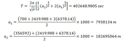
where a is the semi-major axis, and µ (µ = GM) is Kepler’s constant. Employing equation 11, the total time duration for a satellite to reach Moon can be calculated:
As such, it will take 4 days, 15 hrs, and 50.82 minutes for the spacecraft to reach the moon. This estimation is based on the assumption that no orbital maneuvers other than a transfer took place. Furthermore, the time it takes to reach second stage burnout was not included when performing the calculations. In view of the above results, our rocket will liftoff from the Reagan Test Site on the 26th of January, 2010, at 1:00 PM local time to make the intersection with Moon. [1] http://wwwn.cdc.gov/travel/destinationMarshallIslands.aspx |
||||||||||||||||||||||||||||||||||||||||