Landing on the Moon
The landing site has coordinates 1.41° N, 23.18° E (IAU Mean Earth Polar Axis Coordinate System) and is the southeastern region of the familiar Mare Tranquillitatus (Sea of Tranquility). The choice to land at this location is based on a variety of factors. In order to earn some of the additional prize money offered by the Google Lunar X Prize, EOSystems engineers will use the rover to document other man-made artifacts on the lunar surface. Our chosen landing site is proximal to both Surveyor 5 and Apollo 11. Additional factors affecting the location choice were the relatively flat terrain in the vicinity, as well as orbital mechanics. By inserting Verge into a nearly equatorial lunar orbit, EOSystems engineers will minimize the number of trajectory altering maneuvers en route, thus minimizing the amount of fuel required, as well as the opportunity for mishaps.
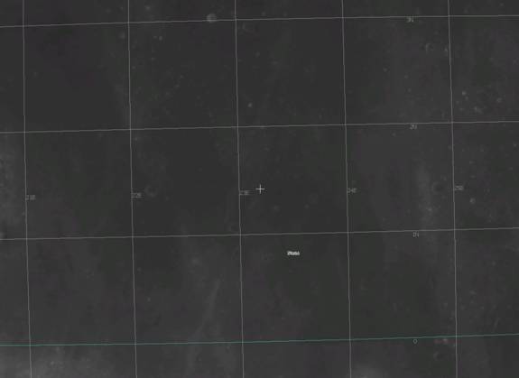
Figure 1: Image of Landing Site, courtesy of NASA’s World Wind Software
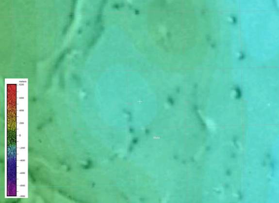
Figure 2: Terrain Map of Landing Site, courtesy of NASA’s World Wind Software
Once Verge is in stable lunar orbit, it will automatically initiate the landing sequence based on the predicted sunrise at the landing coordinates. In order to minimize the time Verge spends in lunar night, the landing sequence will be coordinated to prevent Verge from touching down in darkness. The onboard microcomputer will depart Earth with predicted sunrise information but will be able to initiate the landing sequence at any time based on instructions received via USN.
The first step of the landing sequence is to reorient Verge to transition from "head-first" to "feet-first" travel. This maneuver will be the final operation completed by the attitude control thrusters used during transit.
To initiate the remainder of landing sequence, the computer will first use a combination of data sources to determine Verge’s lunar subpoint position. Telemetry data from USN and the onboard optical celestial navigation system will provide the bulk of the position information. The remainder location ambiguity will be resolved by comparing the received long range tracking radar signature with the extensively mapped equatorial lunar surface.
At the appropriate time, Verge will initiate the major deceleration burn, utilizing a solid propellant rocket at the base of Verge’s lander. This deceleration burn will reduce Verge’s velocity from 1,633 m/s to 50 m/s. Following this burn, the long range tracking radar will assist in Verge’s attitude control, providing a ground-truth test to verify the onboard gyroscopes and other telemetry data. The remainder of Verge’s maneuvers during the descent will be accomplished via three Vernier-style thrusters using the identical fuel types as the aforementioned attitude control thrusters: hydrogen peroxide and RP-1. Based on success of previous lunar missions, EOSystems will use variable thrusters capable of producing between 100 N and 400 N of thrust. One of the thrusters will be on a pivoting mount, providing rotational thrust in both directions. Once Verge is properly oriented and has descended to an altitude of 800 m, the solid rocket module will be jettisoned to minimize touchdown mass. At this point in the descent, Verge will have diminished its orbital velocity to match that of the lunar surface, and will be making minor latitude and longitude position adjustments.
As Verge continues its descent, the long range radar will be jettisoned at an altitude of 600 m. Subsequently, the two radar altimeter units will be energized, providing a stereo radar picture as the decent continues. Specifically, the Verge lander will incorporate a radar altimeter designed by Roke Manor Research (RMR), Limited. Due to EOSystems’ low-mass and low-cost objectives, Verge will utilize two space-rated Type 1 Miniature Radar Altimeters (Figure 3) designed by RMR. The radar altimeters will be mounted on the underside of the lander polygon, to accurately determine Verge’s height above the Moon. With 12.5 cm altitude resolution, the MRA – Type 1 provides accurate height information up to a range of 700 m (~2300 ft). If, for any reason, this radar altimeter is later determined to not meet real-world requirements, RMR is capable of meeting EOSystems requirements through their Bespoke Design Service3.
For more MRA – Type 1 specifications, see the table below.
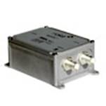
Figure 3: Roke Manor Research, Ltd.’s Miniature Radar Altimeter – Type 1.
Radar altimeter specifications:
| Nominal Range |
1.5-700 |
m |
| Width |
0.075 |
m |
| Height |
0.120 |
m |
| Depth |
0.046 |
m |
| Input Voltage |
9-32 |
VDC |
| Input Power (max) |
10 |
W |
| Operating Temperatures |
-40 -> +75 |
°C |
| Storage Temperatures |
-40 -> +85 |
°C |
The stereo radar approach will serve two purposes: component redundancy and increased accuracy. Though both radar antennas will be on the same platform, and thus will not truly operate as a stereo pair having two radars can still be used to increased resolution. This is accomplished using a method known as Synthetic Aperture Radar Interferometry. Each antenna receives its own signal and the signal from the other radar; therefore, there is a certain amount of information to be extracted in the difference between the two received signals. By matching equivalent pixels between the two received signals, the minor phase variations at each pixel indicate partial interference. This interference is a result of the different path lengths the signal traveled and infers differing heights. By canceling out the curvature of the Moon and other error factors, the remaining differences can be interpreted as terrain elevation4. This will allow Verge’s onboard computer to use simple algorithms and real-time EOSystems interaction to avoid less than optimal terrain, such as craters or other hazards. Additionally, the onboard computer will be able to use this detailed information to calculate Verge’s velocity vector as the descent progresses.
Once Verge has maneuvered to an acceptable landing location and descended to an altitude of 3 m, the Vernier thrusters will completely arrest the descent and shut off. Based on previous lunar missions, operating thrusters near the surface of the Moon has a noticeable side effect of kicking up lunar dust. In order to prevent lunar dust from causing erroneous altitude data, the altitude radars will deenergize once the final landing sequence is initiated. Onboard telemetry and gyroscopic sensors will be used to verify that the timed burn occurred correctly. The accumulated velocity resulting from the 3 m free fall (3.1 m/s) will be safely absorbed by the soft landing system.
The soft landing system consists of large footpads and collapsible sections within the support legs. The footpads have sufficient area to prevent sinking in the soft lunar surface and will have spikes protruding down to arrest any residual transverse motion after touchdown. The support legs employ an outer sleeve that is mounted to the body of the lander and will be able to slide down the solid leg mounted to the footpads. Within the outer sleeve will be tubes of crushable honeycombed aluminum. This landing technique proved very successful for all of NASA’s Surveyor missions, and it provides a low cost landing solution. As the footpads touchdown, the kinetic energy of the lander will be absorbed by the aluminum’s crushing. This will be done in such a way to reduce the deceleration shock to the lander.
Return to top
[1] http://www.roke.co.uk/mra/
[2] http://www.roke.co.uk/download/datasheets/066-mra-type1.pdf
[3] http://www.roke.co.uk/download/video/play.php?s=mra&q=hi&w=360&h=288
[4] http://rst.gsfc.nasa.gov/Sect11/Sect11_8.html
[5] http://nssdc.gsfc.nasa.gov/nmc/masterCatalog.do?sc=1967-112A
|