 |
|

| |
|
|
|
|
|
|
Telemetry, Tracking and Control Telemetry, Tracking and Control (TT&C) services will be contracted through Universal Space Network (USN). Their infrastructure is similar to NASA's Deep Space Network (DSN) with high gain parabolic dishes around the globe. USN's business model consists of contracting their services, including telemetry, tracking and control (TT&C), spacecraft operations and management, and mission-unique development and integration, to privately owned companies. In transit to the Moon, the primary omni-directional antenna, onboard the lander, will be used for telemetry, tracking, and control. This antenna provides the benefits of not requiring high directionality as well as low bandwidth communications. This system allows the spacecraft to send a heartbeat signal and receive commands at all times. During transit, communications must be maintained regardless of the spacecraft attitude. The RF link is the only way that data is obtained from the modules. Thus, the telecommunications system is emphasized. Comparing DSN to USN, one will find that the DSN has larger dishes resulting in a higher gain and, therefore, a longer range for deep space missions. However, as demonstrated below, our analysis will prove that USN has many times the capabilities required for a lunar mission. Also, as a private company, one can assume USN would offer their services at a more reasonable rate as a competitive advantage over NASA. This reduction in cost does not include the fact that USN is offering TT&C services to competitors in the Google Lunar X Prize at a 50% discount. Another point of consideration is that NASA requires all missions planning to use DSN test their equipment on site no less than 18 months prior to launch. USN does not state such a requirement. As a normal design procedure, we plan to test our system reliability against USN's system prior to launch; however, committing to using their services does not constrain us on time as NASA would. For the reasons above, EOSystems has chosen negotiate a contract with USN to provide TT&C services for our mission. This will require both an S-band uplink and downlink. The link budget analysis is described below. USN partnered with PrioraNet to deliver dish antennas on every continent. Using the specifications attained directly from Dave Massey at USN, we were able to create our appropriate link budget. Any variable below with a subscript "ES" (Earth Station) below refers to values off this table.
Most USN stations do not support turbo coding, which we would prefer to implement since it provides us a higher recovery rate at a lower carrier to noise (C/N) ratio. Due to their limitations, we will be using a rate-1/2 convolutional code for our forward error correction. This link will be used to transmit short commands including trajectory correction while in flight and instructions for the rover while on the lunar surface; therefore, it will only require a small bandwidth. The link will use a rate-1/2 convolutional coded QPSK modulation with a raised cosine rolloff factor of 0.3.
Using the link budget equation described below, we can determine what to expect as our minimum C/N ratio.(r=R*103 meters) (C/N)u = (EIRP)ES+(Gain)R-20*log10(4π*r/λ)-10log10(kBT) (C/N)u= 20.7 dB Our S-band receiver will receive these commands on the lander or rover, if the lander is malfunctioning. A diagram of the receiver is shown below.
L3's MSR-765 will support demodulation and decoding the received signal. It will output xhat which will be fed directly into the lander's computer. The computer will process the command and determine which task to perform. These tasks could include sending commands to the rover, realigning the high gain antenna, or enable/disable the X-band transmitter. The receiver antenna is the same S-band antenna used to transmit to USN described in the next section. Telemetry will be sent through this link to monitor the health of our system. However, in the case that our high gain antenna fails and is no longer able to transmit the video stream through Allen Telescope Array, this link will replace it. Both the lander and the rover will be equipped with an omni-directional antenna for communication with USN. The rover will normally receive commands through the lander; however, in case of complication or complete failure with the lander's system, we have provided a backup system on the rover. In this situation, the rover's S-band receiver will be functional at all times but the transmitter will require the engine to shut off before powering up. This design is in place so failure with the lander or high gain antenna will not cause the entire mission to fail. Our link budget is designed with a 7.65MHz bandwidth to enable the lander to support the video stream with 4.5Mbps. This will require us to use a storage device to queue data, as a live stream would normally be 20Mbps. The bandwidth is determined by selecting a rate-1/2 convolutional coded QPSK modulation with a raised cosine rolloff factor of 0.3.
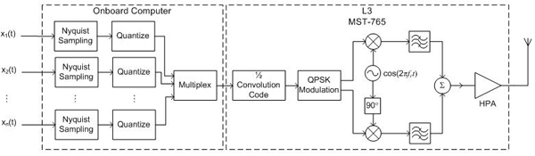
Using our link budget equation, we can now determine the minimum EIRP required of our transmitter. (r=R*103 meters) EIRP = (C/N)ES+10log10(kB)+20log10(4π*r/λ)-(G/T)ES EIRP = 32.8 dB Since we know the gain of our antenna is 25.8 dBi, we can conclude that the output power required is 6.98 dBW (4.99 W). The rover will be further limited because of using an omni-directional antenna with a gain closer to 0 dBi. Therefore, it can only transmit data at 7.69kbps resulting in a 20kHz bandwidth. This will increase the time required to transmit to 45 minutes for the same amount of data the high gain antenna could send in 1 second. Due to this, we must limit the rover to only transmitting images. This would be our worst case scenario if both the high gain and omni-directional antennas on the lander were to fail. A typical block diagram of our transmitter is shown below. The analog telemetry inputs, x1(t), x2(t), ..., xn(t), are sampled and quantized to be converted into digital signals. They are then multiplexed into a single digital signal to be transmitted. A rate-1/2 convolutional code was chosen as the forward error correction due to the limitations within USN. This is applied once the signal is multiplexed to add redundancy, improving the recovery rate of each bit at low C/N ratios. The coded bits are then modulated using a QPSK modulator before being amplified for transmission.
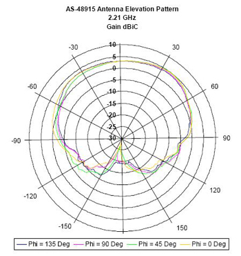
EOSystems engineers have decided to use as many pre-built systems as possible in order to reduce the time each component would require to be built, tested, and certified. The computer onboard the lander will support this system by digitizing and multiplexing the input telemetry data. This single digital telemetry stream is then transmitted to L3's MST-765 S-band Transmitter via RS-422. This transmitter will code, modulate and amplify the signal before outputting to the antenna. The rover and lander will use two different S-band antennas. The lander will again use the Ulysses based antenna design explained in the HGA section. The rover will communicate with USN using EDO Corporation's omni-directional AS-48915 (spec sheet), an conical, spiral antenna with the following pattern.
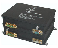
On both the lander and the rover, we will be using L3's Miniature S-Band T&C Transceiver, MSX-765 (spec sheet), for forward error correction, modulation, and amplification. It consists of both the MST-765 and MSR-765 functioning separately.
We will request the following options: QPSK and Forward Error Correction. As previously stated, the forward error correction will be a rate-1/2 convolutional code as this is the best USN will support. The specifications have been reviewed and meet our requirements. [1] http://deepspace.jpl.nasa.gov/advmiss/docs/5_3-MOC_Services_SMEX_AO_2007.pdf |
||||||||||||||||||||||||||||||||||||||||||||||||||||||||||||||||||||||||||||||||||||||||||||||||||||||||||