 |
|

| |
|
|
|
|
|
|
Coding a digital signal provides the redundancy needed in order to reconstruct the signal at the receiver. For the forward error correction code on our video signal, we have chosen to use a rate-1/2 turbo code to maximize the probability of recovering our data. A 1/2 rate means that for every one bit of data there will be two bits delivered: the bit itself and a redundant bit. A block diagram of a typical turbo code design is shown below [Fig 1]. It consists of two recursive systematic convolutional (RSC) encoders and an interleaver. 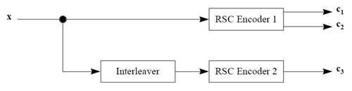 Convolutional Encoder A conventional RSC encoder model is shown below. The recursive convolutional encoder was chosen over a nonrecursive encoder due to it having a lower bit error rate (BER) at low signal-to-noise (SNR) ratios. These codes can be described with a rate (r) and the number of previous bits (K) used to determine each output. The diagram below has r=1/2 and K = 3. The D blocks represent shift registers. Notice there are two outputs: c1 and c2.  Interleaver Interleavers have many different designs: block, random (pseudo-random), circular-shifting, semi-random, odd-even, or optimal. The odd-even interleaver design was developed specifically for rate-1/2 turbo code. In order to build an r=1/2 system, a punctuated r=1/3 system must be used. Similar to our desired system, a rate of 1/3 implies that for each bit, two extra bits of redundancy will be sent. Such redundancy would allow for a lower received carrier-to-noise (C/N) ratio at the cost of increasing bandwidth. A punctuated turbo code is one that removes some of these redundancy bits in order to obtain a desired lower bandwidth. The odd-even interleaver first uses the block interleaver design to permute the input sequence, as shown below.
The numbers represent a sequence of bits. The block interleaver inputs the bits by column and outputs them by rows.
After the RSC encoders, the coded bit sequences, c2 and c3, are output. x yields c2 and xint yields c3, where xint is the interleaver output. The coded bits can be referred to as the systematic stream. The odd-even interleaver will then select every odd coded bit from c2 and every even coded bit from c3 and multiplex them together. The output is shown below.
This table demonstrates how each bit has one corresponding coded bit, which is the expected result for our r=1/2 turbo code. The signal is decoded after being passed through a channel. All channels are introduce to additive noise and a reduction of signal power. A receiver must be able to determine what the original signal is using the both the data stream with the redundant bits to check for errors. Decoding a signal is much more difficult than encoding; therefore, the derivation will not be shown (see reference [1]). A diagram is shown below to implement the soft-output Viterbi algorithm (SOVA) decoder.  The received bits are demultiplexed into y1, y2 and y3. These inputs include the systematic stream and two parity check streams from the two encoders, respectively. [1] http://scholar.lib.vt.edu/theses/available/etd-71897-15815/unrestricted/etd.pdf
|
||||||||||||||||||||||||||||||||||||||||||||||||||||||||||