 |
|

| |
|
|
|
|
|
|
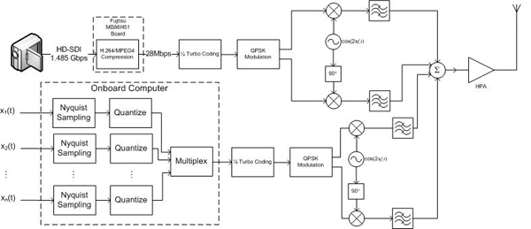
Video Stream Two systems will be built to transmit video stream between the rover and Allen Telescope Array (ATA). The first is to be implemented on the rover in order to transmit the data to the lander. The lander will receive the signal, demodulate and decode then code and modulate the signal again. This redundancy assures that errors are minimal in the second link. Also the raw signal can be stored on the lander if there is no line-of-sight with ATA. If there is line-of-sight, the modulated signal is immediately passed through the high gain antenna to be received on Earth. ATA is the first implementation of a large-N radio telescope on land. Based on a scalable architecture, it was built by the Search for Extraterrestrial Intelligence (SETI) Institute and began operation with 42 dishes in October 2007. The workings of Moore's Law will drive ever-increasing functionality and performance in ATA-hardware as the array will ultimately consist of 350 dishes. The ATA facility, located in the existing Hat Creek Radio Observatory in northern California, can only receive high-definition imagery and video from the Moon during intervals approximately 12 hours long, due to the Earth's rotation relative to the Moon. EOSystems operators must ensure the data link usage is maximized during this time. To avoid transmitting data when there is no line-of-sight to the array, the lander's microcomputer will consult a synchronized system clock to determine when data transmission is possible. Additionally, protocols will be implemented to allow a command to be sent via S-band using Universal Space Network (USN) to activate and deactivate transmission. As specified on the Google Lunar X Prize homepage, the total mooncast transmitted by the private spacecraft will amount to 1 GB of video, imagery, and other data. ATA is offering 500 MB to be transferred absolutely free to any X Prize participant; therefore, there is a 50% price reduction for the data transmission. These things considered, EOSystems engineers believe ATA is the main candidate for use as a downlink for transmitting our high-definition video and imagery. We will now walk through the link from capturing the HD video to receiving it at ATA. The video camera is mounted on the rover, where our link will begin. If the rover loses contact with the lander, the rover retains its ability to use its S-band transceiver and lower data rate to transmit images via USN. Below is the block diagram of the transmitter for the link between the rover and lander. The transceivers for this link use identical hardware, though the bandwidth requirements differ since the lander will not transmit video to the rover. However, the lander will transmit commands and telemetry, if needed. In order to reduce component price, and based on the number of commercial devices available, EOSystems engineers will utilize the 2.4GHz frequency band for this link. The majority of the commercially available products are intended to support IEEE 802.11a/b/g protocols, which is not optimal, so EOSystems will construct our link from individual components. The RF signal will contain two channels: video and telemetry data. The input analog signals (x1, x2, ..., xn) are n telemetry signals that must be sampled, quantized, and multiplexed into a digital signal. This signal will then be coded with a rate-1/2 turbo code with QPSK modulation and raised cosine rolloff factor of 0.3 to be transmitted. fc and ft correspond to the carrier frequencies for the video stream and telemetry, respectively.
The camera we have chosen is the Sony HDC-X300 HD Multi Purpose Camera (spec sheet). We will use the HD-SDI output which streams at 1.485Gbps. EOSystems engineers realize transmitting this bit rate wirelessly is practically impossible. Therefore, we found Fujitsu's MB86H51 (spec sheet), a CMOS chip to support real time H.264/MPEG4 compression. This chip will soon be integrated on a board to support a high rate HD-SDI input. Our HD video will be compressed to a maximum of 20Mbps. This provides us a more realistic wireless transmission bit rate for long range communication. The antenna, Hypergain's HGV-2404U (spec sheet), will be used to transmit and receive, with an identical one on the lander. It has a gain of 4 dBi and has a horizontal antenna pattern shown below:
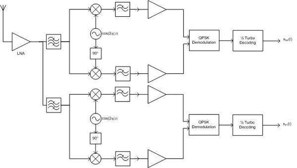
The video is received at the lander for further processing before transmission to ATA. This receiver is designed to separate the video stream from telemetry, and its diagram is shown below. Two outputs are formed from this receiver: xhat is the video stream and xtm is the telemetry.
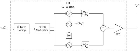
xhat is sent in parallel to the computer and the X-band transmitter. If no line-of-sight exists with ATA, the computer will shut off the transmitter and will store the data. Generally, the lander will command the rover not to send video when there is no line-of-sight; however, this redundancy is implemented to store data in the case that the rover is damaged before line-of-sight is gained. The second transmission of the video stream shown below is from the lander to ATA. This is an X-band signal to allow for high data rates to be sent over a long distance. Our carrier frequency, fc, is 8.495GHz.
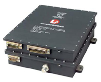
L3's CTX-886 will be used as the X-band transmitter, as it meets our link budget requirements which are further described at the bottom of the page. Like the TT&C transceiver, this integrated solution was chosen because it reduces the number of components and time they would require to be built, tested, and certified. The high gain antenna used in this system is similar in design to the antenna used on the Ulysses space probe. More information can be found by viewing the HGA page. Upon receiving the video stream, ATA will demodulate, decode, and store the data. The receiver diagram is not shown as it is part of ATA's systems and will not be built by EOSystems. Rover <-> Lander First, we will analyze the link budget between the rover and lander. Again, this is a two way communication link, but the analysis is the same for both. This link is designed with a maximum distance of 1 km. If the distance exceeds 1 km we may lose line-of-sight.
Using the following link budget equation, we can find our C/N ratio (r=R*103) PR = PT + GT + GR - 20log10(4π*r/λ) PR = -92.052 dBW (6.235*10-10 W) Knowing the received power and noise power, we can calculate the C/N ratio is 46.377 dB. EOSystems engineers recognize that this far exceeds our requirements; however, this assures us that obstacles, such as rocks and slightly further distances, will not disrupt the communication. Lander -> ATA Now we will analyze the second link budget from the lander to ATA. There are currently 42 dishes, of 350 expected, installed within ATA. According to a source at the SETI Institute, it will be at least 3 years before the entire array is complete, but this timeline is dependant on the availability of funding. Therefore, all calculations below are based on the current array. Each antenna is a Gregorian parabolic dish with a 6 meter diameter. The system temperature specified was obtained from the SETI Institute and is a measured value at the given frequency. Any calculations with a subscript "ES" (Earth Station) refers to values from this table.
As explained above, this link will provide EOSystems engineers with a high data rate in order to transmit a high definition video stream. We have chosen to use a rate-1/2 turbo code with QPSK modulation and a raised cosine rolloff factor of 0.3. As previously described, the data rate we will be transmitting is 20Mbps, yielding a bandwidth of 52MHz. The turbo code was chosen to allow as little as 1dB carrier to noise (C/N) ratio received at ATA. The table below summarizes our link budget analysis.
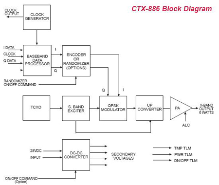
Using these values, we have calculated our maximum EIRP is: EIRPmax=(C/N)R-GES+10log10(kBTES)+10log10(4π*r/λ) EIRPmax=21.7 dB Knowing the transmit gain of our high gain antenna is 40.2 dBi, we can determine the minimum transmit power required for this link is -18.5 dBW or 0.0142 W. After seeing this conclusion, we realize that we can transmit this video stream with ease through ATA. EOSystems engineers have chosen to use the CTX-886 (spec sheet) to support forward error correction, modulation, and amplification in this link. The specifications listed for this product meet all of our link budget requirements described above. It can support data rates up to 320Mbps and outputs a 6W RF signal. Paired with the high gain directional antenna we have chosen, it is clear that this system can easily support our needs.
The block diagram of the CTX-886 is shown below. This device will allow us to easily synchronize all our system through its clock output. The various telemetry outputs would be monitored via USN for any inconsistencies, allowing EOSystems engineers to quickly shut down the system if needed. The 28V DC input power will be supplied directly from the solar panels, restricting this system's use to after the lander has unfolded.
As explained earlier, the forward error correction we have chosen to implement is a rate-1/2 turbo code. You can refer the Turbo Code page to see how it is developed. [1] http://www.seti.org/news/media-information/ata-factsheet.php
|
||||||||||||||||||||||||||||||||||||||||||||||||||||||||||||||||||||||||||||||||||||||||||||||||||||||||||||||||