
Antenna Design
Introduction
A major part of this year's design project is the design and measurement of a receiver antenna for use on the surface of Mars. We built two versions of a probe-fed rectangular patch antenna described in the CMU documentation. This design is inexpensive to fabricate, durable, and still satisfies our project needs. The antennas were tested at the Carnegie Mellon Remote Educational Antenna Lab.
Antenna Physical Specifications
Two fabricated designs were measured at CMU’s REAL facility and one was chosen as our final design. The physical design parameters of the antenna design are as follows:
Substrate Material: Cuming Foam
Dielectric Constant εr = 1.06
Tangent Loss δ = 0.0001
Substrate Height h = 1.58mm
Length L = 61.375mm
Width W = 62.5
Antenna Simulations
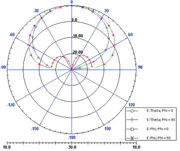
The CMU documentation which describes this antenna design includes simulation data from Ansoft Designer. The first plot shows return loss vs. frequency to identify the resonant frequency of the antenna. The second plot shows the radiation patterns at the resonant frequency.

Measured Data:

The resonant frequency of our antenna was calculated from an S-Parameter measurement at CMU. The minimum return loss (equivalent to maximum power delivered) occurs at 2.233 GHz. That will be the frequency of operation for our positioning signal. Measured data indicates a minimum S11 of -8.672 dB, versus the simulated -36 dB.
Likewise, antenna pattern measurements show a weaker than expected gain. Maximum gain is just over 2 dBi at a 0 degree angle, compared to nearly 10 dBi for the simulated antenna.
Based on the measured data, we selected a minimum acceptable gain of -13 dBi for the receiver antenna. For a satellite to be considered "in-view" of the receiver, it must be at least 17 degrees above the horizon, the region where gain is greater than -13 dBi. The cartesian plot below the two polar plots shows our boundary of acceptable gain.

