
 Communication Systems
Mars Receiver Antenna Design
When deciding on an antenna model for our design, several things were taken into consideration. The design had to provide a broad radiation pattern for good coverage, yet it had to be light, yield good gain, and be easily integrated into the rest of our design. Patch antennas are popular due to their ease of fabrication, simplicity and customizable nature. These are also inexpensive, lightweight and easily integrated with other electronics. All of these advantages make them perfect candidates for numerous applications including Satellite Communications.
While the bandwidth of regular patch antennas is not as high as some other antenna types, there are several alterations one can do to its geometry and design to increase the percentage it covers. To attain this, aperture coupling may be used in the feeding network. This entails having an aperture cut in the ground plane where the patch lies (usually in its center). The patch itself is in a substrate on top of the ground, and then below the ground a second substrate that holds the feedline. This prevents the connector from having to be in the same plane as the patch, and thus lowers all the reflections that come from it. Also, it can eliminate the need for matching networks, such as quarter-wavelength transformers, which significantly reduce the bandwidth. Matching is made by simply varying the dimensions of the aperture in the ground plane. To improve the bandwidth even more so, thicker foam substrates have been implemented. These are classically used when broader bandwidths are needed. The combination of these two provides for a broader bandwidth and slightly greater gain.
Simulations
Before fabricating our device, preliminary simulations were done using Ansoft’s High Frequency Structural Simulator (HFSS). This software is a finite element method solver for electromagnetic structures. The substrates used in the design were foam, and the patch is made from copper.

Simulated Radiation Pattern
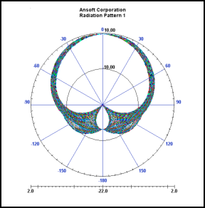
Taking the beam from -60 to 60 degrees, we get an average gain of 5.13 dB.
Simulated Reflection Coefficient S11 (dB)
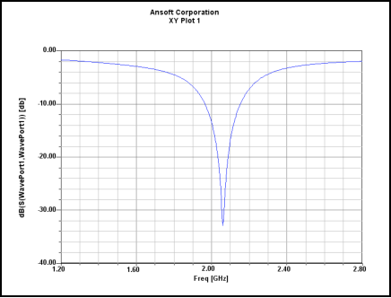
The design is centered at 2.06 GHz. Its bandwidth expands from 1.95 GHz, to 2.17 GHz. This gives it a 10.68% bandwidth (~210 MHz significantly greater than regular patch antennas). This broader bandwidth gives us flexibility in our design, by enabling us to use more frequencies (if we needed to).
Fabrication
The fabrication for this design is straightforward. It required foam (substrates), copper tape (patch), sheet of copper (ground plane) and an SMA connector. Once everything was cut to their respective sizes, the tape was placed on the substrates, and the ground aligned accordingly. Finally, the connector was soldered.
Actual Measurements
The antenna’s reflection coefficient was measured with a network analyzer, calibrated from 1 to 3 GHz. Its output file was then processed by a simple matlab code to get the reflection dB values, and plot against frequency (patch_data.m).

Antenna is centered at 1.99 GHz. Its bandwidth (low reflections, below -10 dB) extends from 1.91 to 2.10 GHz. Giving it a ~ 9.54 % bandwidth. As expected, the fabricated antenna’s centered frequency shifted a little.
 Once the in-house measurements were completed, the antenna was sent to Carnegie Mellon University's antenna range for pattern measurements (shown on left). The resulting radiation pattern is shown below

The shape of the pattern and its beam-width agree with simulated results. Again, as expected, the average gain attained for the fabricated antenna is slightly lower (4.7 dBi)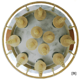
Satellite Transmit Antenna
The satellite main trasmit antenna consists of a circular array of 12 helical elements. These two rings of elements are fed 180º out of phase, providing a 20º beam angle [B]. This antenna weighs 15kg and has a diameter of 1.34 meters. This antenna provides circular polarization, which means that the receiver orientation does not matter as much.
[A] "A wide-band single-layer patch antenna," IEEE Trans.
Antennas Propagat., vol. 46, pp. 471-473, 1998.
[B] http://www.ngs.noaa.gov/IGSWorkshop2008/docs/schmitz_gppigs08_bii_p.pdf
[C] "A Broadband Patch Antenna with Wide Slits," IEEE Trans.
Antennas Propagat., vol. 3, pp. 1414-1417, 2000.
[D] "Analysis of an Aperture Coupled Microstrip Antenna,"
IEEE Trans. Antennas and Propagat., vol. 34, pp. 977-984, 1986.
[E] "Single-layer single-patch wideband microstrip
antenna," Electron. Lett., vol. 31, pp. 1310-1312, 1995
[F] http://ipnpr.jpl.nasa.gov/progress_report/42-149/149C.pdf
Inter-satellite Link Analysis
The inter-satellite communications are done using a packet-based mesh network. A data rate of 1kbps is sufficient for inter-satellite communications. Only trajectory, diagnostic, and time synchronization data needs to be sent over this link. Using a mesh architecture allows for minimum distance line-of-sight communications and shortest path routing. Any satellite needing to relay a message to Earth will generate a request that will be sent through the satellite mesh network to the satellite nearest the Mars lander. This root node satellite will relay the message to the lander that will then relay the message to Earth on the high power 1Mbps link.
| Nomenclature | |
| Tn= Physical Noise Temperature for Space-Space Link [B] | 54K |
| B = Bandwidth | 1000bps / 2 sym/Hz * 2 = 1 kHz |
| Pn = Noise Power | k x Tn x B = 7.452 x 10⁻¹⁹ W = -181.277 dBW |
| SNR = Required SNR for QPSK | 20dB |
| Gt= gain of transmitting antenna | 0 dBi |
| Gr= gain of receiving antenna | 0dBi |
| Rmax = Maximum distance between any two adjacent satellites | 20125.6 km |
| f = frequency | 300 MHz (λ = 1 m) |
| Pt= Transmitted Power | Unknown |
| Pr=Received Power | Unknown |
Pr= -181.277dBW + 20dB = -161.77 dBW
Pt= -161.77 - 20log(4π/λRmax) = -37.68dBW = 170μW
This is an extremely low transmit power thanks to the low noise temperature for space to space communications. To ensure future upgradability as well as a reliable link margin, the transmit power has been chosen to be 0.5 Watts. This will not result in a large problem with the power budget. 0.5W is negligible compared to the system power production capacity. The RF hardware required for this link is simple. A TNC modem connects to a BPSK modulator that connects to a 0.5 W RF amplifier. This amplifier connects to a low gain, light-weight, 1/2-wave omni-directional antenna.
Earth to Mars Two Way Link Analysis
| Nomenclature | No = noise-power-density, dBW/Hz |
| erfc = complementary error function | Pt = transmitted power, dBW |
| f=specified frequency, km | Tb = bit period |
| r= range, GHz | Link Throughput : 4 Mbps |
| Eb = energy-per-bit, dB | Data Throughput : 2.6 Mbps |
| Gt= gain of transmitting antenna, dBi | Modulation Scheme : QPSK |
| Gr= gain of receiving antenna, dBi | Error Control Coding: Rate 2/3 Turbo Coder |
| Lt = loss from transmitting, dB | BER: 10-6 |
Introduction
The communication system supports transmission of data at rates greater than 1 Mbps. The link has been designed to support 4 Mbps with QPSK modulation and Turbo coding using aimed dish antennas. The purpose of the link analysis budget is to determine whether the transmitter/receiver system provides sufficient signal to noise ratio to achieve an acceptable bit error rate. The budget analysis calculates values such as the effective isotropic radiated power, communication losses, bit error rate, antenna gain, and other information relative to sizing a high gain antenna. Before trying to size an antenna, we first must verify our capabilities and calculations with a current example of a link budget analysis. Once all the data, equations, and calculations match the sample analysis and we understand them completely, we can then apply the same process to our mission and make the necessary changes in the data and parameters.
Link Budget Analysis
Prad = Pt
EIRP = Pt x Gt [W]
In decibels: EIRP = 10 x log(Pt) + 10log(Gt) [dBW]
FSL=32.4 + 20 x log(r) + 20 x log(f)
Pe = ½
erfc x ![]()
where the erfc value can
be found in tabular or graphical form in mathematical tables. For typical transmission systems the
BER may lie on in the range of 10-3 – 10-9. For our mission we establish a bit
error rate of approximately 10-6, therefore the required Eb/No would be approximately 2 dB (with turbo coding) as seen in the link
budget analysis.
Transmitter and Receiver Antenna Gains
 The antenna parameter that relates the power output
(or input) to that of an isotropic radiator as a purely geometric ratio is the
antenna directivity or directive gain. The importance of using highly directional antennas is
that they provide signal power gain. For a paraboloidal antenna the isotropic gain is
given by G = h*(10.472 x f x D)2 where f is the carrier
frequency in gigahertz, D is the reflector diameter in meters, and the h is the aperture
efficiency. For our purpose of this link
budget, 0.55 is used for the aperture efficiency.
The antenna parameter that relates the power output
(or input) to that of an isotropic radiator as a purely geometric ratio is the
antenna directivity or directive gain. The importance of using highly directional antennas is
that they provide signal power gain. For a paraboloidal antenna the isotropic gain is
given by G = h*(10.472 x f x D)2 where f is the carrier
frequency in gigahertz, D is the reflector diameter in meters, and the h is the aperture
efficiency. For our purpose of this link
budget, 0.55 is used for the aperture efficiency.
The 34m NASA Deep Space Network High Efficiency (HEF) transmitter antenna gain at the uplink frequency can range from 61 to 65 dBi, and the gain the antenna receives at the downlink frequency lies between 75.2 and 80 dBi. Given the earth station gain, the required diameter of the folding dish on Mars is 3.39 m. This is large, but not prohibitively so. It can be transported with the Mars probe in the nose of the final rocket.
Deep Space Network
NASA Deep
Space Network is used for communicating with the system from Earth. The NASA DSN network
consists of three deep-space communication facilities located at
Goldstone, U.S.A., Madrid, Spain, and Canberra, Australia. The DSN currently
consists of three deep-space communications facilities placed approximately 120
degrees apart around the world: at Goldstone, in California’s Mojave Desert;
near Madrid, Spain; and near Canberra, Australia. This strategic placement permits constant observation of
spacecraft as the Earth rotates.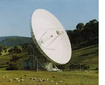
The DSN 34m High Efficiency (HEF) Sub network antenna in the USA, Australia, or Spain is the ground communication medium used to communicate to and from Mars. There is a large demand for the 70m antennas from DSN, and the Mars Global Positioning System requires that communication be readily available. The 34m HEF antennas can uplink at frequencies ranging from 7145 to 7190 MHz and receive downlinks from 8400 to 8500 MHz. The transmit power from the antennas ranges from 20-200 kW.
High Gain Antenna
The high gain antenna (HGA) on the lander is necessary to support all communication links back to Earth. The antenna weighs approximately 80 kg and has a fully deployed diameter of 3.35 m.
The link budget analysis shows the HGA receives data at a frequency of 7.2 GHz (C-band). The HGA transmits at 8.5 GHz (X-band).
Data Transmission
Both the uplink and downlink support 4 Mbps of data throughput. The minimum Bandwidth required is 2 MHz with QPSK being the the modulation scheme. The output Symbol rate is 2 Msps. With a roll off factor of 0.55 the bandwidth requirement is 3.1 Mhz. The minimum SNR at the Earth station with 2/3 turbo coding is 2 dB. An additional link margin of 4 dB is provided in the design. The maximum real data rate will be 2.6 Mbps.
| Uplink Data | Link Budget |
Nomenclature |
| Uplink Distance from Earth to Mars, km | 401300000 |
r |
| Frequency, GHz | 7.20 |
f |
| Transmit Power, dBW | 46.57 |
Pt |
| Transmitter Antenna Gain, dBi | 65.58 |
Gt |
| Terminal EIRP, dBW | 112.15 |
EIRP |
| Received Isotropic Power, dBW | -178.85 |
Pri |
| Received Signal Power, dBW | -133.4 |
Pr |
| Receiver Antenna Gain, dBi | 45.45 |
Gr |
| Received Eb/No, dB | 6 |
(Eb/No)r |
| Link Margin, dB | 4 |
M |
| Downlink Data | Link Budget |
Nomenclature |
| Downlink Distance from Mars to Earth, km | 401300000 |
r |
| Frequency, GHz | 8.50 |
f |
| Transmit Power, dBW | 41.61 |
Pt |
| Transmitter Antenna Gain, dBi | 46.89 |
Gt |
| Terminal EIRP, dBW | 88.5 |
EIRP |
| Received Isotropic Power, dBW | -211.5 |
Pri |
| Received Signal Power, dBW | -133.4 |
Pr |
| Receiver Antenna Gain, dBi | 78.10 |
Gr |
| Received Eb/No, dB | 6 |
(Eb/No)r |
| Link Margin, dB | 4 |
M |
Using the uplink and downlink numbers above, the link margin is shown to be 4dB in both directions. This link margin will protect ensure a low bit error rate and will provide a reliable channel.
RF Hardware
The main Mars-Earth link consists of a QPSK modulator which connected to a mixer which increases the frequency to 8.5GHz. This is then passed into a four stage amplifer with filtering. The first stage boosts the power to 1 watt. It is then bandpass filtered and passed through a mid-power amplifier which raises the power to 50W. This is again filtered and passed into another amplifier stage that boosts the power to 1.5kW. This is then sent to a high power final stage that sends the full 14.5 kW out to the folding dish antenna.
[G] Drake,
B., “Human Exploration Technology – Goals and Requirements,” http://www.reston.com/nasa/heds/09.11.9heds.reqs.html,
September 1997
[H] Flock, W.
L., “Propagation Effects on Satellite Systems at Frequencies Below 10 GHz,”
NASA Reference Publication 1108(02), 198
[I] Roddy,
D., “Satellite Communications,” 2nd ed., McGraw-Hill, New York,
1996.
[J] Wolff,
S., “Deep Space Network Home Page,” http://deepspace.jpl.nasa.gov/dsn/index.html,
March 12, 2001.
[K] http://cobweb.ecn.purdue.edu/~aae450s/fall01/sp01cd/report/sec7_1.doc