Communication System
The communication system for this mission has several unique challenges. The biggest unknown is whether or not it will be fully functional after hundreds of years of deep space. After that duration, it must be able to transmit signals light years across the galaxy at high power. Both of the segments, the spacecraft communication system and the ground communication system, have to be able to track each other's movement across the sky with a high level of precision in order to point the antennas accurately. The proposed spacecraft and ground communication systems use current space-proven technology to address these challenges. Each system is described in the sections below, followed by a link budget analysis.
Frequency Band
The spacecraft will operate in the Ka-band; uplink frequency of 32 GHz, and a downlink frequency of 34 GHz. This is consistent with the current Deep Space Network (DSN) spectrum allocations. Ka-band was chosen since it is the highest frequency currently used in the DSN. Optical communication may become the preferred method in the future for deep space communications, however, the infrastructure is not currently in place for optical communications. Space-bourne optical receivers wil likely be required for deep space communications to avoid cloud attenuation. In addition, concerns regarding pointing accuracy errors over multiple light years and the infancy of deep space optical communications led to the decision to use Ka-band. The required pointing accuracy for an optical communication link is fractions of a micro-radian, versus milli-radians for Ka-band. (Ref 1)
Spacecraft Communication System
The key features of the spacecraft communication system are described below, including the baseband processing module, the power amplifier, and the antenna.
Baseband Processing
All the baseband processing is performed on redundant radiation hardened Application Specific Integrated Circuits (ASICs). The trend for space based digital communications is to use highly reconfigurable Field Programmable Gate Arrays (FPGAs). However, FPGAs are not as robust as ASICs regarding long term exposure to radiation.
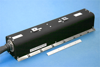
The baseband processing module is shown in the Figure below.

Baseband Processing
For the downlink, the selected modulation scheme is Offset QPSK. Offset QPSK is a variant of QSPK which has no zero crossings. This is a "TWTA-friendly" modulation scheme that has minimal spectral regrowth, and permits the waveform to run in saturation (peak RF outut).
For the uplink, BPSK is selected. Although it would easy to use QPSK or a variant and double the data rate using the quadradture channel, it would also increase the complexity of the spacecraft receiver. Since the ground station will have plenty of antenna gain and transmit power, there is no need to use QPSK.
The data rate for the baseband processign module will be reprogrammable and adaptive. The Spacecraft Controller will be capable of detecting faults, such as a degradation in RF outut power. When such a fault is detected, the radio could autonomously drop the data rate to compensate. Due to the light year gap in communications, a closed loop decision is not feasbile. The maximum bit rate at Epsilon Eridani will be less than 1 kbit/s, and possibly as low as 10-25 bps.
Error free communications for deep space missions are made possible with powerful error correction codes. The selected error code is a rate 1/6 Turbo code. LDPC codes were also considered; however, the low rate Turbo codes in general outperform low code rate LDPC codes. (ref 3). Low code rates are prefered for low data rate applications, and the Turbo codes investifgated also perform better than the higher rate codes. The code is capable of 10^-6 performance at an Eb/No of 0 dB.
Spacecraft Amplifier
Travelling Wave Tube Amplifiers (TWTAs) are high-power broadband amplifiers that have a strong space heritage. TWTAs are much more efficient than solid state amplifiers (60% vs 14%), have much greater output power (500 W vs 2-3 W), and their construction is more radiation tolerant (ref. 5)
Ka-band TWTA
The highest space qualified Ka-band TWTA output power is around 500 W. ref L-3) The overall transmit power can be greatly increased through power combining with a device such a Magic-Tee. The Magic-Tee is a waveguide four port device which can be used to combine the power of two in-phase signals, such as the output from two TWTAs.
The proposed spacecraft amplifier is a power combining circuit consisting of ten operational 500 W TWTAs, with additional TWTAs as spares. All ten would only be necessary at the destination - far less would be required en route to Epsilon Eridani. The resulting RF transmit power is 5 kW. Although a single high power amplifer such as a multi-beam coupled-cavity TWT or a Klyston could provide the same amount of RF power, the device would have been a single point of failure and would likely fail before reaching the destination.
There is a practical limit to how many TWTAs can be power combined. Multipaction and RF breakdown can occur at high power levels. An analysis on this subject was not included in this preliminary study.
TWTAs typically have life spans of up to 15 years. It is recommended that options be considered for extending the life of the TWTA (low power modes, etc). The shelf life of TWTAs for hundreds of years is unknown, but it is expected that the spare, unused TWTAs will still have 15 years of operation when they are activated. The spare TWTAs will be automously actived when a failure is detected.
Spacecraft Antenna
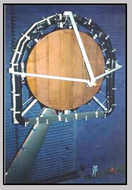
The selected antenna is a space-deployable inflatable antenna. Due to the required size of the spacecraft antenna (10s of meters in diameter), inflatable antennas were the only feasable antenna due to the mass requirements of a traditional dish reflector. Various spacecraft antenna designs were studied. The reflectarray antenna was selected due to it's flat surface structure. Relectarrays are flat and have many microstrip antenna elements across the surface. The flat structure will be easier to maintain in space over a long duration, instead of maintaining a curved reflector surface.

Close up of microstrip patch antenna
The proposed reflectarray antenna size is 44 meters by 44 meters. NASA has invested in constructing a 3 meter Ka-band reflectarray antenna - this research would be leveraged to extend the technology to a much larger apperature. It should be mentioned that inflatable reflectarray antennas only have overall efficiencies of 30-40%.
http://www.ilcdover.com/products_ad_space_kaband.cfm
Ground Communication System
The ground communication system for this mission will include multiple ground stations scatterred across the planet. NASA's Deep Space Network (DSN) already has three locations in Barstow, CA USA, Madrid, Spain, and Canberra, Austrailia. In addition, at least three additional facitilies are required, at locations to be determined. The current facilties at these locations do not support the needs of a deep space mission to Epsilon Eridani. Significant upgrades will be required, including the construction of large antenna arrays, and infrastructure upgrades. The proposed system is described below:
Antenna Array
In order to pick up the signal from the spacecraft 10.5 light years away, an extraordinary amount of of antenna gain is required. Instead of constructing one large antenna array, which would be unwieldly, expensive and dificult to maintain, a large array can be constructed with many smaller antennas yielding the same effective area. NASA has performed studies on the optimum diameter for such an array, and determined that a 12 meter diameter dish minimizes the cost function. (ref 4). The geomery of the dish is Cassegrain.
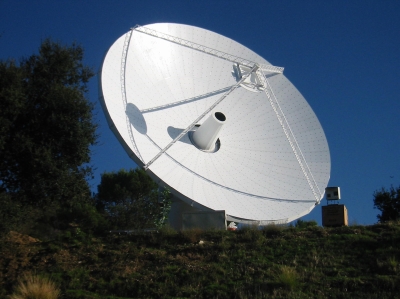
NASA has considered constructing a 400 element antenna array, as shown by an artist in the figure below. The proposed size of this antenna array is 4000 antennas, a 10x increase.

Artist concept for DSN antenna array: Credit: NASA/JPL
For the three additional facitilies, it is proposed that NASA work with the radio telescope SKA Square Kilometer Array (SKA) and other similiar projects. SKA is a global collaboration of 20 countries that are building a radio telescope in Austrailia. The SKA will not support Ka-band until 2022. In general, the interests of the DSN and the radio astronomy are well aligned, but do not perfectly overlap. Significant cost savings could be obtained by leveraging the SKA and similiar projects.
Power Amplifier
The power amplifer for the ground segment is proposed to be a high power Klystron or similair electron device. A 100 kW of RF power is assumed.
Baseband Processing
The waveform baseband processing will require significant amount of processing. Turbo codes take many iterations to decode, so a highly parallel decoding algorithm may be required to reduce latency.
Atmospheric Effects
One disadvantage of Ka-band is rain fade. The wavelength of Ka-band frequencies are small enough that rain drops have a scattering effect. Using the Simplified Attenuation Model (ref 2), we see that an appropriate rain fade margin is around 6-7 dB from the Link Budget section. However, the rain fade margin is not included in the actual link budget. This is because of the ground station antenna diversity - it is very unlikely that all of the ground stations would be experiencing rain at the same time.
Link Budget
The link budget for the system is shown in the table below.
|
|
S/C to Earth,
Downlink |
Earth to S/C,
Uplink |
Units |
|||
|
Constants |
|
|
|
|||
|
Boltzmans k |
1.38E-23 |
1.38E-23 |
m2 kg s-2 K-1 |
|||
|
c |
299792458 |
299792458 |
m/s |
|||
|
Spacecraft Antenna Gain |
||||||
|
Area |
1936 |
1936 |
m^2 |
|||
|
Frequency |
3.40E+10 |
3.20E+10 |
Hz |
|||
|
Efficiency |
0.50 |
0.5 |
% |
|||
|
Gain |
81.94 |
81.42 |
dB |
|||
|
Transmit Power (Spacecraft or DSN) |
||||||
|
10
TWTAs/Klystron |
66.99 |
|
dBm |
|||
|
DSN Antenna Gain |
||||||
|
N |
4,000.00 |
4,000.00 |
||||
|
Ae/Antenna |
113.10 |
113.10 |
m^2/Antenna |
|||
|
Area |
452389.3421 |
452389.3421 |
m^2 |
|||
|
Frequency |
3.40E+10 |
3.20E+10 |
Hz |
|||
|
Efficiency |
0.64 |
0.64 |
% |
|||
|
Gain |
106.70 |
106.18 |
dB |
|||
|
Path Loss |
||||||
|
Distance |
9.93E+16 |
9.93E+16 |
m |
|||
|
Loss |
339.94 |
339.94 |
dB |
|||
|
Frequency Loss |
||||||
|
Loss |
63.08 |
62.55 |
dB |
|||
|
Receiver Noise (Spacecraft or DSN) |
||||||
|
Temp |
37 |
37 |
K |
|||
|
Noise Density |
-182.92 |
-182.92 |
dBm/Hz |
|||
|
Simplified Attenuation Model |
||||||
|
a= |
2.14E-01 |
1.85E-01 |
||||
|
b= |
1.01E+00 |
1.02E+00 |
||||
|
R= |
22 |
22 |
mm/hr |
|||
|
L |
1.5 |
1.5 |
km |
|||
|
Link Budget |
||||||
|
Signal |
-147.38 |
-144.90 |
dBm |
|||
|
Rx Imp Loss |
1 |
3 |
dB |
|||
|
Atm Effects
(rain fade) |
7.24 |
|
dB |
|||
|
Margin |
3 |
3 |
dB |
|||
| Point Loss *Est. | 1 | 1 | dB | |||
|
Required Eb/No, 10^-6 Performance |
0 |
0 |
dB |
|||
|
C/No |
31.53 |
|
dB-Hz |
|||
|
Max Data |
1130.73 |
|
bps |
|||
|
Data Transfer |
||||||
|
File Size |
1 |
1 |
MB |
|||
|
File Size |
1048576 |
1048576 |
bits |
|||
|
Time to
transfer |
|
|
s |
|||
|
Time, minutes |
|
|
minutes |
|||
Conclusions
With 3 dB margin, and some reasonable assumptions, the maximum data rate supported is around 1 kbps. To reiterate: rain fade is not included in downlink due to ground station diversity. Other assumptions: 1 dB pointing loss total. More research is required to estimate the pointing loss for light year distances where close loop algorithms do not easily work.
References
(1) Deep Space Optical Communications by Hamid Hemmati
(2) Satellite Communications by Timothy Pratt
(3) Development of Turbo and LDPC Codes for Deep Space Applications by KS Andrews
(4) The Deep Space Network Large Array, Mark S. Gatti.