SLASR
Overview
This satellite will use a fairly new solar panel technology developed specifically for high-power applications in space. This technology is called Stretched Lens Array SquareRigger, or SLASR. Its development began in 2003 with a team including people from NASA, Entech, ATK, Emcore, and Ion Beam Optics. Since 2006, SLASR has reached a level of maturity where it is feasible for upcoming deep space missions.
SLASR has achieved an unprecedented level of performance in photovoltaics and is therefore the best option for a power system that will have to be very efficient. Below is some current specifications for this technology:
· Areal Power Density = 300 - 400 W/m2
· Specific Power = 300 W/kg - 500 W/kg
· Stowed Power = 80 - 120 kW/m3
· Scalable Array Power = 4 kW to 100’s of kW’s
· Super-Insulated Small Cell Circuit = High-Voltage (300-600 V) Operation at Low Mass Penalty
· Super-Shielded Small Cell Circuit = Excellent Radiation Hardness at Low Mass Penalty
· 85% Cell Area Savings = 66% to 75% Lower Array Cost per Watt than One-Sun Array
· Modular, Scalable, & Mass-Producible at MWs per Year Using Existing Capacities
Background and History
SLASR is a unique type of solar cell array that is called a refractive photovoltaic concentrator system, which has been in existence since the 1980s. The idea behind this is that a Fresnel lens is used to concentrate incoming sunlight to provide a higher density of energy on the solar cells. Therefore, the output of the solar array can be increased without changing the size of the solar cells, equivalent to increasing efficiency. One of the first tests of this technology was in 1994. Developed by several of the same team members from Entech and NASA, a mini-dome lens array was tested on a year-long flight in a high-radiation elliptical orbit (70° and 363 km by 2,550 km). This mini-dome lens array is shown in Figure 1.
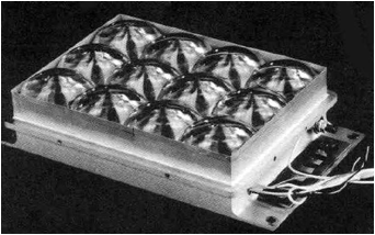
Figure 1. Mini-dome lens array from 1994 test flight.
The test was a success, with the array demonstrating high performance and reliability. This led to continued development of refractive concentrator systems. Another essential test of the technology was the SCARLET array, which was used on NASA’s Deep Space 1 probe successfully throughout the 38-month mission (1998-2001). The array provided power to the spacecraft and ion drive.
Stretched Lens Array
One of the unique advancements of SLASR is the Stretched Lens Array (SLA). While previous lens concentrator systems used fragile glass arches, SLA consists of an array of small lenses in which the connection between lenses is actually flexible enough to be foldable. The result is something comparable to Venetian blinds. While the blinds can start off covering the whole area of the window, when the slats are tilted horizontally they can be stacked upon one another and fit in a very small space. In terms of solar arrays used in space, this concept is revolutionary, as it allows very large solar panels to be compressed into a tight space. This is critical for getting more and larger solar arrays through the launch process and into space. Figure 2 shows a deployment over time of a Stretched Lens Array.
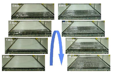
Figure 2. Deployment of a Stretched Lens Array over time.
SquareRigger
SquareRigger is system developed by ATK Space Systems that provides a deployable frame to house flexible solar cell arrays. Originally developed for the Air Force Research Lab to use for thin-film solar arrays in space, it works even better with Stretched Lens Arrays. In Figure 2, the rectangular frame at 0 minutes is the entirety of the SquareRigger frame. It can be seen that even though the SLA is perfectly compact at this point, the frame is still as large as the whole array, at a size of 2.5 m by 5.0 m. To fix this, the frame needs to be compactable, and the SquareRigger system accomplished this. Figure 3 shows the SquareRigger frame unfolding from a small, thin cylindrical shape.
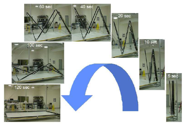
Figure 3. Deployment of SquareRigger frame over time.
Additional Details and Results
Using both SquareRigger and Stretched Lens Array technology, it is now possible to fit an entire 2.5 m by 5.0 m solar cell array into a very compact volume. Amazingly, each one of these arrays provides about 4 kW of power in orbit. And since each array is so compact up until deployment in orbit, it has been theorized that a satellite with two solar array wings could hold 12 SquareRigger bays on each wing, resulting in an unheard-of 100 kW power output. This could truly revolutionize the power available to all satellites. From performance of prototypes, the stowed power density is expected to be around 80 kW per cubic meter.
The SquareRigger frame is composed of carbon composite structural tubes that provide support and protection during launch. Once in orbit, one motor is used to deploy both the frame and SLA. Once fully deployed, everything locks into place.
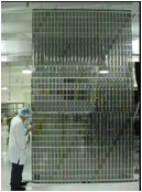
Figure 4. Fully deployed Stretched Lens Array.
One important aspect of the solar cell arrays is the ability to protect the solar cells from ultraviolet wavelengths of light, which can damage the silicon lens material. This is a requirement for all solar arrays, especially ones that could be exposed to high radiation levels such as in deep space missions. SLASR accomplishes this using a thin coating developed by Ion Beam Optics, which blocks approximately 90% of UV radiation. Simulations along with four years of testing on the International Space Station show that it works well.
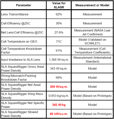
Overall, SLASR is looking very promising, and working prototypes show that it is reaching maturity quickly. It will be an ideal power source for deep space missions, especially for providing power to high power communication systems. It will also be necessary for collecting energy in the Epsilon Eridani system, whose star only has about one third the luminescence of the Sun. The exoplanet in the system is also at an estimated distance of 3.5 AU from the star, meaning there will be less solar energy density here compared to sunlight around Earth. Having many solar arrays and high efficiency provided by SLASR will allow for a large amount of power to still be gathered in these conditions. More SLASR performance parameters are available in Table 1 below, based on either measurements, prototypes, or models.
Table 1. SLASR Performance Parameters
Credit for information and figures goes to the team who presented on SLASR at the 4th World Conference on Photovoltaic Energy Conversion in Hawaii on May 7-12, 2006.
Team: Mark O’Neill1, Joe Howell, John Fikes, Louis Lollar, Connie Carrington, Nantel Suzuki, Michael Piszczor, David Hoppe, Michael Eskenazi, Dan Aiken, Michael Fulton, Henry Brandhorst, Michael Schuller, A.J. McDanal