Attitude Determination and Control System
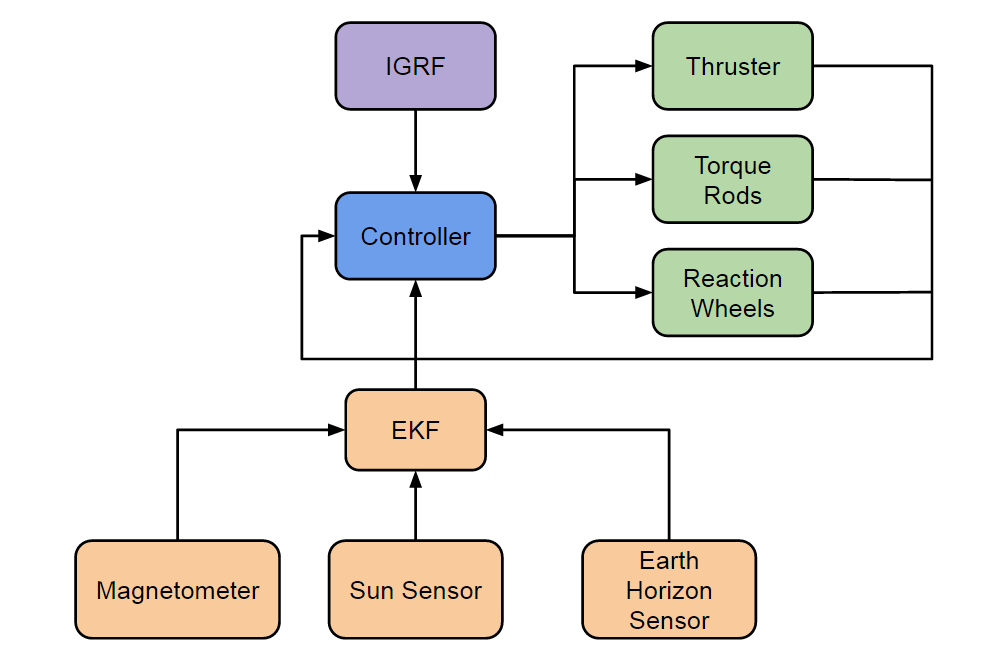
The Attitude Determination and Control System (ADACS) is the combination of a processor, sensors, and actuators that come together to calculate and set the attitude or orientation of the satellite.
Controller
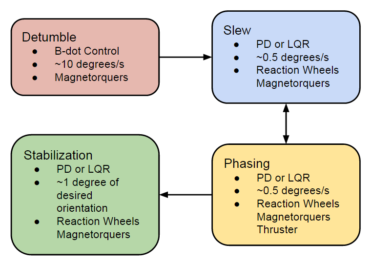
The main controller of the ADACS has four functions similar to the LightSail-1[1]. After deployment, the cube satellite will detumble to dampen out any initial spin rate. The cube satellite will then perform a slew maneuver into the appropriate orientation in preparation for the phasing manuever to place the satellite in the correct position in orbit. After phasing, the satellite will slew once more to point toward Earth and remain pointing for the rest of its life span. The four modes are detumble, slew, phasing, and stabilization(pointing).
Detumble Mode
The Detumble Mode is implemented with a B-dot controller using the magnetic actuators. The B-dot control is implemented by applying a magnetic torque in the opposite direction of the rate of change of the magnetic field[2]. The rate of change of the magnetic field can be estimated by the magnetometer. The torque is generated from the cross product of the magnetic dipole and Earth's magnetic field.
As shown in [2], B is the instantaneous magnetic field vector, ω is the angular rotation of the satellite, m is the desired dipole generated from the torque rods, τ is the control torque.
Slew Mode
The rotation maneuver is optimally performed using an eigenaxis rotation[2]. An eigenaxis rotation is taken as the shortest angular path between two orientations. The controller can be implemented as a linear quaternion feedback regulator which can be designed through a proportional gain matrix and derivative gain matrix.
Also in [2], u is the control torque, Ω is the torque due to gyroscopic forces, J is the inertia, ω is the angular rotation rate of the system. Kd and Kp are the derivative and proportional gain matrices respectively and δq is the measured attitude error.
Phasing Mode
Orbital phasing is performed with a two-impulse Hohmann transfer to bring the spacecraft away and back to the original orbit. This mode begins after the slew maneuver has rotated the cube satellite to point the thruster tangent to the orbit. After the first thrust, another slew maneuver is performed to aim the thruster in the opposite direction and a second thrust brings the satellite back into the correct orbit. The Phasing Mode manages the position of the cube satellite with knowledge of the positions of the other satellites in the constellation. The controller must maintain the correct heading during the thrust to properly perform the manuever.
Stabilization Mode
The pointing controller uses a similiar control law as the slew maneuver except with different control gains. This controller follows a periodic trajectory to maintain Earth pointing. This mode prioritizes stabilization by the time each picture is taken.
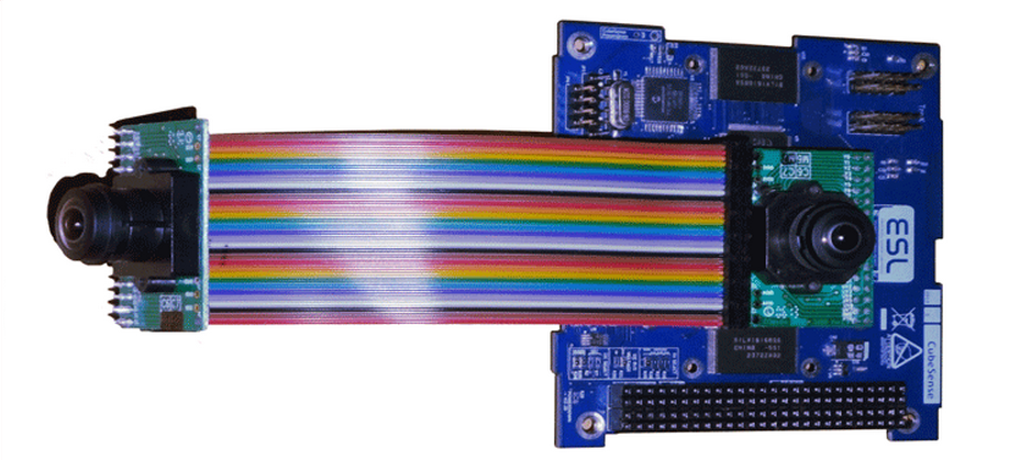
Sensors
The cube satellite will incorporate six 2-axis sun sensors, four Earth horizon sensors, a two-axis Earth nadir sensor, and two 3-axis magnetometers which mirrors the AeroCube-OSCD cube satellite setup. The AeroCube-OSCD has continuous attitude determination with ~1o accuracy and a reported pointing accuracy of ~0.1o [3].
An Extended Kalman Filter (EKF) is used to to process noisy sensor readings and provide a better estimation of the system state. The EKF is expected to converge from any initial attitude error to a conservative B-dot control settling velocity (~0.7 deg/s) [4]
| Sensor | Accuracy |
|---|---|
| Magnetometer | <1o |
| Sun Sensor | <0.5o |
| Earth Horizon Sensor | <0.3o |
Magnetometer
The 3-axis magnetometer measures the magnetic field strength of the Earth which provides an orientation reference for the cube satellite relative to the Earth.
| Characteristic | Specification |
|---|---|
| Range | +50,000 nT to -50,000 nT |
| Sensitivity | 6.5 nT |
| Update Rate | 10 Hz |
| Noise Density | <500 pT RMS/Hz |
Sun Sensor
The Sun sensor determines the Cube Satellite body angles relative to the Sun. This sensor has a field of view of 114o and four to six sensors can achieve full sky coverage.
| Characteristic | Specification |
|---|---|
| Field of View | ±57o |
| Update Rate | >10 Hz |
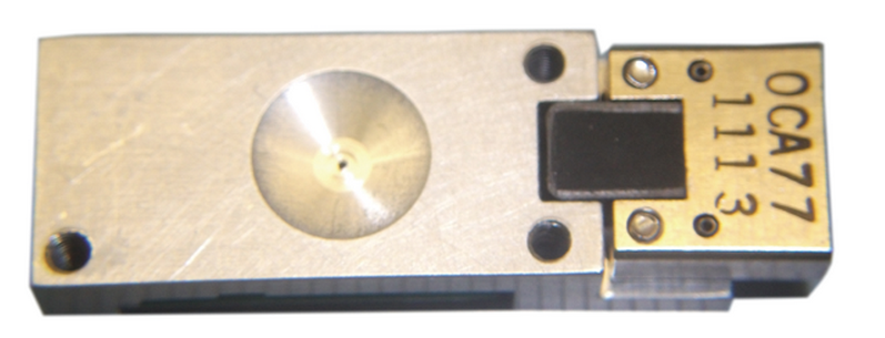
Earth Horizon Sensor
The Earth horizon sensor generates a nadir vector relative to the sensor's coordinate frame. This sensor has a 190o field of view and is packaged with a Sun sensor.
| Characteristic | Specification |
|---|---|
| Field of View | 190o |
| Update Rate | 2 Hz |
Actuators
To provide complete 3-axis pointing capability, this cube satellite contains three magnetorquers (torque rods), three reaction wheels, and a thruster.
While it has been shown that less actuators can theoretically stabilize the cube satellite in three axes (three torque rods and polar orbit[5]) (three torque rods and one reaction wheel[6]), this design incorporates the extra reaction wheels to increase robustness and performance of the control system.
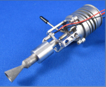
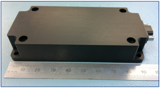
Thruster
The thruster is used to spread the satellite constellation into the correct positions after deployment. The thruster module is a self contained unit that takes up 1U of space to fit all the components including propellant tank, electronics and valve.
| Characteristic | Specification |
|---|---|
| Total Impulse | 505 N-s |
| Nominal Thrust | 0.5 N |
| Nominal ISP | 220 s |
| Delta-V | 130 m/s |
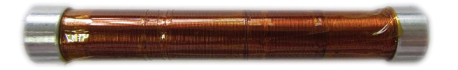
Magnetorquers
The magnetorquers or torque rods generate a magnetic dipole which interacts with Earth's magnetic field to create a torque in the orthogonal direction. Torque rods are energy efficient, reliable, and primarily used to detumble the satellite after deployment. In a polar orbit, the magnetorquers can potentially stabilize all three axes, except at the magnetic north and the equator where the magnetic field is parallel with one of the axes[5].
| Characteristic | Specification |
|---|---|
| Nominial Magnetic Moment | ±0.24 Am2 |
| Saturation Magnetic Moment | ±1.5 Am2 |
| Linearity | 2.5% |
| Residual Moment | <0.48 mAm2 |
| Resistance | 30-31 Ohm |
| Inductance | 0.15 H |
| Magnetic Gain Constant | 2.9024 Am2/A |
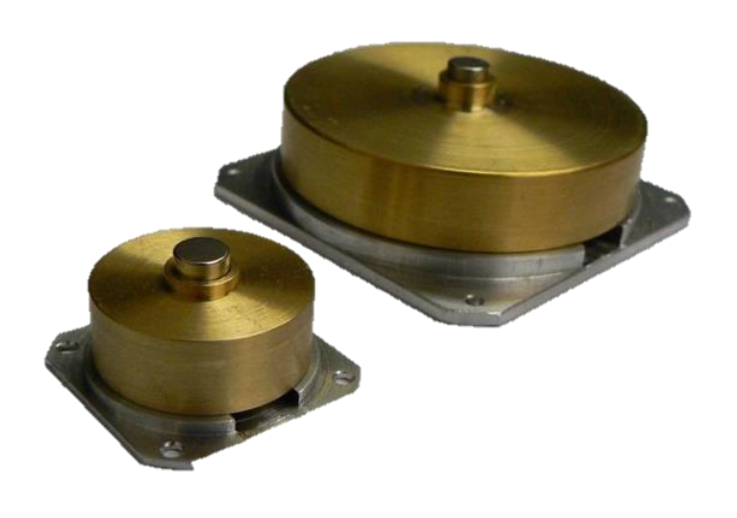
Reaction Wheels
Reaction wheels or momentum wheels generate torque by turning a flywheel in the opposite direction. Reaction wheels require more power than torque rods but can provide more torque. They are generally more expensive than torque rods and can experience mechnical failure [7].
| Characteristic | Specification |
|---|---|
| Speed Range | ±8000 RPM |
| Speed Control Accuracy | <5 RPM |
| Max Torque | 2.1 mNm |
| Momentum Storage | 40 mNms |
Magnetic Model
A magnetic model is often used to simplify control gain calculation in the B-dot controller[9]. For the controller design, the International Geomagnetic Reference Field (IGRF) is selected over the other magnetic models for its accuracy and its availability as a free model. The IGRF is updated every five years.
References
[1] Nehrenz, Matthew T. Initial Design and Simulation of the Attitude Determination and Control System for LightSail-1. Senior Design at California Polytechnic State University, 2010.
[2] Quadrino, Meghan K., David Miller, Kerri Cahoy, Testing the Attitude Determination and Control of a CubeSat with Hardware-in-the-Loop. Master of Science Thesis at Massachusetts Institute of Technology, 2014.
[3] Kramer, Herbert J., AeroCube-OCSD (AeroCube-Optical Communication and Sensor Demonstration). Earth Observation Portal, 2014.
[4] Babcock, Erik P.,CubeSat Attitude Determination via Kalman Filtering of Magnetometer and Solar Cell Data. Conference on Small Satellites Submission University of Illinois Urbana-Champaign.
[5] Makovec, Kristin L., A Nonlinear Magnetic Controller for Three-Axis Stability of Nanosatellites. Master of Science Thesis at Virginia Polytechnic Institute and State University, 2001.
[6] Young, Brady W., Design and Specification of an Attitude Control System for the DANDE Mission. Master of Science Thesis at University of Colorado, 2008.
[7] Capo-Lugo, Pedro A., John Rakoczy, Devon Sanders, The B-dot Earth Average Magnetic Field. NASA.