Power System
Overview
Over the course of one 93-minute period, the power system has an expected end of life (EOL) generating capability of an average of 17.82 Watts and a peak of 28.1 Watts, which feeds the average load of 11.91 Watts, and peak load of 24.47 Watts. During periods without sun visibility, a 10Whr space-certified battery operates a reduced load of 3.2 Watts.
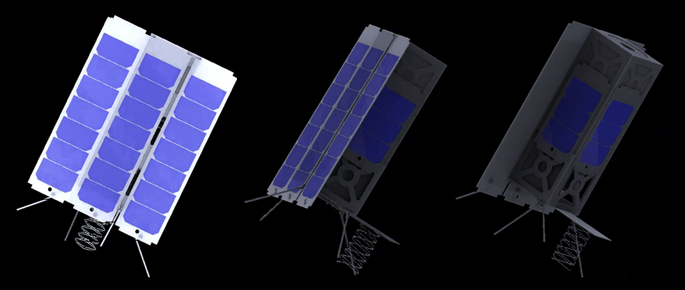
Primary power generation is provided by the 3 main solar panels with active sun pointing. In addition, half-length solar panels are included on the remaining 3 rectangular faces as shown in Figure 1. The panels can generate up to 4.68 W in the unlikely event the satellite becomes disoriented for an extended period of time. This power would supplement or recharge the battery until correct sun-pointing is restored.
Power Generation
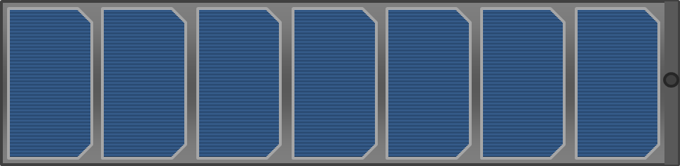
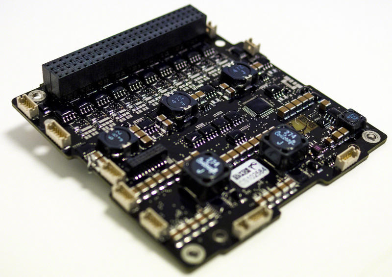
3U cubesat solar panels typically include an array of seven triple junction solar cells laid out on a printed circuit board (PCB) as shown in Figure 2. A panel is the length of the satellite, 30cm x 10cm. The exact dimension and spacing of the cells will vary by cell manufacturer and customer specifications. To simplify solar panel comparison calculations, we estimate that the photovoltaic cells will cover 90% of the panel surface area.
For direct sunlight, solar panel power output can be determined by calculating the cell surface area by the cell efficiency and solar constant as shown in equation 1. The solar constant defines the typical average flux density arriving from the sun to a LEO satellite as 1361 W/m2 [1].
Panel Output = Panel Cell Area x Cell Efficiency x Solar Constant (1)
Our satellites feature three 30cmx10cm panels with sun pointing, for a total panel surface area of 900 sq cm, of which 810 sq cm will be photovoltaic cells.
In addition, the effects of performance degradation due to radiation in space must be considered. Although the degradation will vary depending on the exact materials and manufacturing processes, within 15 years most LEO triple junction space-grade cells can be assumed to be operating at 87% of their beginning of life (BOL) efficiency [2,3]. Because the satellites are expected to operate for 10 years, we calculate power consumption as if nearing EOL.
Using the assumptions listed above, a solar panel comparison chart is listed below by vendor. For cells sold without a PCB, the pricing for a space-grade PCB was added based on average panel PCB pricing .
Table 2. Solar panel vendor comparison for a 30cm x 10 cm panel.
Vendor |
Panel Type |
BOL Efficiency |
Estimated EOL Efficiency |
EOL Output (W) |
Cost per Panel |
|---|---|---|---|---|---|
Clyde Space |
3U CubeSat Complete Solar Panel |
28.30% |
24.62% |
9.05 W |
$6050* |
Azur Space |
InGaP/GaAs/Ge on Ge substrate triple junction 3G30A |
29.30% |
25.49% |
9.37 W |
$2219* |
Spectrolab |
NeXt Triple Junction (XTJ) Solar Cells |
29.50% |
25.67% |
9.43 W |
$2700* |
SolAero |
Advanced Triple-Junction Solar Cell for Space Applications |
29.50% |
25.67% |
9.43 W |
Not Available |
*Disclaimer: the price values are ballpark estimates obtained using company websites or rough quotes. Prices listed here are for educational purposes only and are not endorsed by any company.
Using 3 solar panels with Azur Space solar cells, up to 28.1 W can be generated at EOL.
Lighting Times
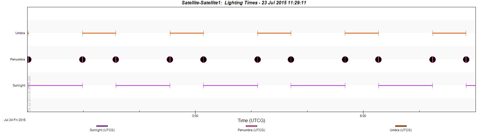
The satellites are in a sun-synchronous noon/midnight orbit, meaning that the satellite will always pass over the equator at noon and midnight local time once per period. Using STK 10, it was determined that this results in approximately 58 minutes of sunlight followed by 35 minutes of darkness per period. A STK 10 lighting time graph for multiple periods is shown in figure 3, with purple bars indicating periods of lighting, and orange bars indicating periods behind earth's umbra. Factoring in lighting times, the average satellite power generation per period is 17.5 W.
Power Consumption
The required component power was calculated using the operating voltage and currents provided by each component's datasheet listed in the Bill of Materials, with voltage regulator efficiency taken into account.The totals in Table 1 reflects the maximum possible power load - when the satellite is simultaneously photographing, processing, transmitting, and reorienting.
Table 1: Peak load power requirements on each voltage bus
| Voltage Bus | |||
|---|---|---|---|
| Component | 12V | 5V | 3.3V |
| Flight Computer | - | - | 0.166 amp |
| Magnetometer | - | 0.14 amp | - |
| Sun Sensor x 2 | - | 0.01 amp | - |
| EHS x 4 | - | 0.288 amp | - |
| Torque Rods x3 | - | - | 0.3 amp |
| Reaction Wheels x3 |
0.45 amp | - | - |
| Camera Sensor | - | - | 0.8 amp |
| Image Processing FPGA | - | - | 0.1 amp |
| Data Transmitter | 0.85 amp | - | - |
| UHF(Receive)Transceiver | - | 0.178 amp | - |
| Total Amps | 1.3 amp | 0.616 amp | 0.95 amp |
| Regulator Efficiency | 94% | 96% | 95% |
| Watts Required | 16.54 W | 3.203 W | 4.735 W |
| Total Power | 24.47 W | ||
Consumption Variations over Time
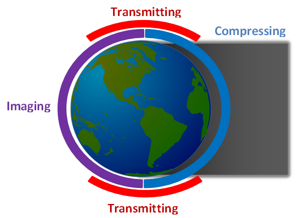
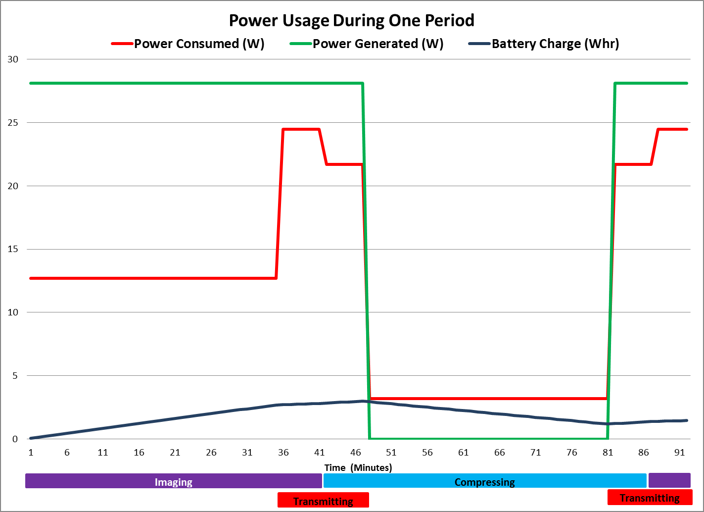
As shown in Figure 4, the satellites' actions can be broken into 3 main catagories: Imaging, Transmitting, and Compressing.
Imaging - Occurs for half a period when over the lit portion of the earth. The satellite is actively using all sensors and orientation components, as well as the camera and possibly the compression FPGA. The data transmitters and receivers are unpowered, resulting in a maximum power consumption of 12.7 Watts.
Transmitting/Receiving - Occurs for 22 minutes per period when over earth's poles, and occurs simultaneously while either imaging or compressing are taking place. During this time, all sensors, orientation components, transmitters, and receivers are powered. While imaging and transmitting, the satellite requires 24.47 Watts, and while compressing and transmitting, the satellite requires 21.7 Watts.
Compressing - Occurs for half a period when over the dark portion of the earth. The satellite is only using sensors, the flight computer, and the compression FPGA. The data transmitters and orientation components are unpowered, requiring only 3.2 Watts.
Available Power
Figure 5 shows how the load, generation, and battery charge change over one orbital period. The generated power in Watts is shown in green, the maximum consumed power in Watts is shown in red, and the battery charge in W/hr is shown in blue. Excess generated power not consumed by the load is used to charge the battery. The battery is calculated at a very low end of life efficiency of 30% [4,5].
Although the figure shows the battery initially uncharged, in reality this would not occur because charge carries over from period to period, and more power is generated than is consumed each period. Furthermore, it should be noted that the 10W/hr battery only discharges around 20% of its capacity each period.Based on the analysis, the system is capable of generating and storing sufficient power at all times throughout the mission's lifecycle.
Power System Distribution
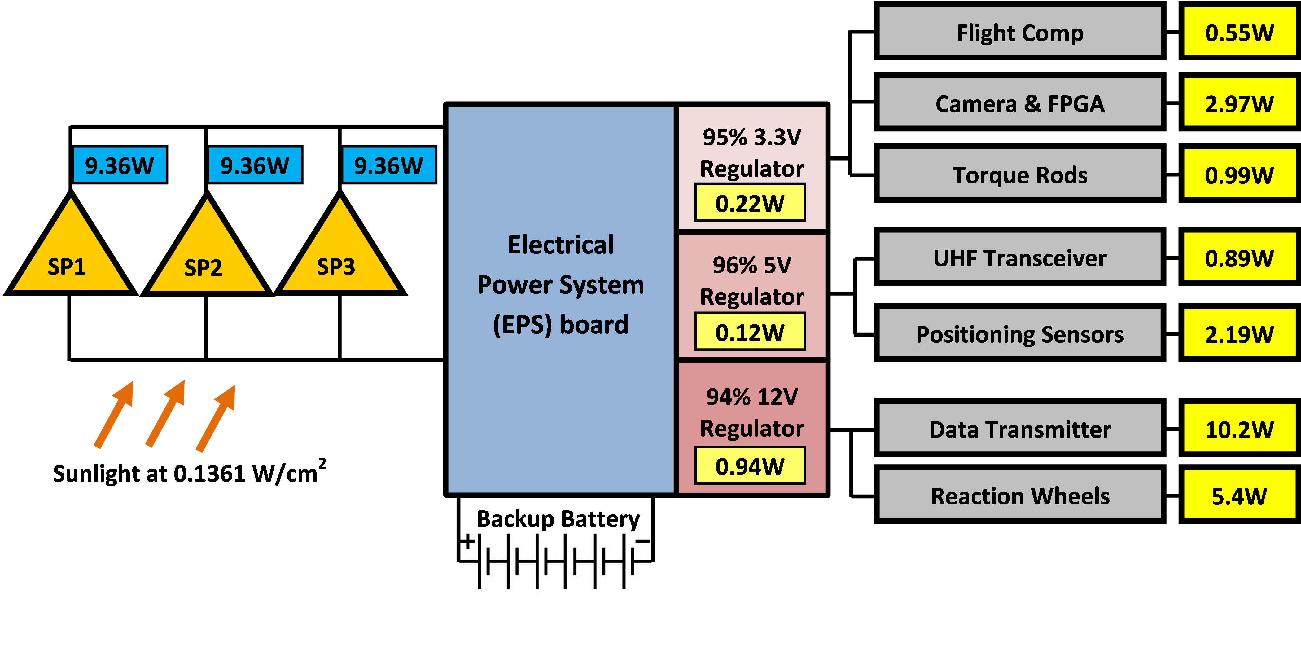
Based on the above sections, the power distribution system must handle a maximum input of 28.1 Watts, and an operating load of 24.47 Watts. Based on the power requirements, the Clyde Space 3G EPS motherboard with an integrated battery daughter board was selected to manage the power system as shown in figure 6 [6].
A power diagram showing the system operating at peak load is shown in figure 7. The figure shows the sun generating 9.36 Watts at each solar panel, which is fed into the EPS board. The power is then regulated to the appropriate voltages, though some power is lost due to regulator inefficiencies. The power is then received by each of the load components.
References
[1] J. Kennewell and A. McDonald, "The Solar Constant," IPS Radio and Space Services.[2]S. Bailey and a. R. Raffaelle, "Space Solar Cells and Arrays," in Handbook of Photovoltaic Science and Engineering, John Wiley & Sons, Ltd, 2003.
[3] Y. Sheng-sheng, G. Xin, F. Zhan-zu, Z. Lei and C. Xin-yu, "Displacement damage analysis of single-junction and triple-junction GaAs solar cells induced by electron irradiation," in Radiation and Its Effects on Components and Systems (RADECS), 2013 14th European Conference on, Oxford, 2013.
[4]C. S. Clark and E. Simon, "Evaluation of Lithium Polymer Technology for Small Satellite Applications," in 21st Annual AIAA/USU Confrence on Small Satellites, 2007.
[5]G. Horvath, G. Marosy, S. Glisics and D. Czifra, "Battery characterization for CubeSat missions with battery tester application," in Electronics Conference (BEC), 2012 13th Biennial Baltic, Tallinn, 2012.
[6]Gonzalez-Llorente, D. Rodriguez-Duarte, S. Sanchez-Sanjuan and A. Rambal-Vecino, "Improving the efficiency of 3U CubeSat EPS by selecting operating conditions for power converters," in Aerospace Conference, 2015 IEEE, Big Sky, MT, 2015.