
System Overview
The CubeSat communications system consists of four components: an X-band transmitter, X-band patch antenna, UHF receiver, and UHF monopole antenna. The X-band transmitter and patch antenna are used to send image data to the receiving ground stations, while the UHF receiver and monopole antenna are used to receive commands from the ground stations. The UHF system is operated only when necessary in order to conserve power. More details on UHF system operation are located on the Satellite Uplink page.
X-Band Transmitter
We chose an X-band transmitter developed by researchers at Utah State University [1]. A diagram of the transmitter is shown below.

X-Band Transmitter Architecture [1]
The transmitter has the following specifications:
- Input Voltage: 8-32V DC
- RF Output Power: 2W
- Operating Power: 10W for +33dBm (2W) RF transmit power
- Frequency Range: 8.025 - 8.400 GHz (X-band)
- User Data Rate: 3 - 50 Mbps (programmable)
- Modulation Scheme: Offset Quadrature Phase-Shift Keying (OQPSK)
- Error Correction: Convolutional Coding
- Filtering: 6th Order Butterworth
Offset Quadrature Phase-Shift Keying
OQPSK was chosen as the modulation scheme for this X-band transmitter. OQPSK is a variant of Quadrature Phase-Shift Keying (QPSK) in which the phase shift is limited to no more than 90 degrees at a time. In QPSK, the phase of the signals can change as much as 180 degrees at once, causing large fluctuations in signal amplitude. Such an amplitude fluctuation is not a desirable characteristic for communication systems [2]. Below is an image comparing QPSK and OQPSK phase changes for an example signal.
OQPSK was chosen as the modulation scheme for this X-band transmitter. OQPSK is a variant of Quadrature Phase-Shift Keying (QPSK) in which the phase shift is limited to no more than 90 degrees at a time. In QPSK, the phase of the signals can change as much as 180 degrees at once, causing large fluctuations in signal amplitude. Such an amplitude fluctuation is not a desirable characteristic for communication systems [2]. Below is an image comparing QPSK and OQPSK phase changes for an example signal.

Figure A: Example Signal Symbol Constellation [2]
|

Figure B: Phase Changes for Signal Shown in Figure A
|
Convolutional Coding
Convolutional coding was chosen as the error-correcting scheme for this X-band transmitter.
Convolutional coding was chosen as the error-correcting scheme for this X-band transmitter.
X-Band Patch Antenna
An X-band patch antenna developed by AntDevCo was chosen [2].
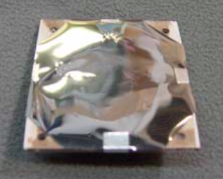
AntDevCo X-band Patch Antenna [2]
The antenna specifications are as follows:
- Gain: 11 dB
- HPBW: 50 degrees
- Center Frequency: 8200 MHz
- Bandwidth: >100 MHz
- Polarization: Linear or Circular (Circular chosen for our application)
- Transmit Power: Up to 10W (2W used in our application)
UHF Receiver and Antenna
The CubeSat platform we chose, the Tyvak Intrepid Platform [3], contains an integrated UHF transceiver and antenna that will be used only for receiving commands from ground stations. The specifications of the UHF system are as follows:
- Gain: 0 dB [4]
- Operating Frequency: 400 - 470 MHz
- Center Frequency: 435 MHz
- Bandwidth: 10 MHz [4]
- RF Output Power: 0.1W, 0.5W, or 1W (user-selectable, but not used in our system)
- Modulation Scheme: OQPSK
- Antenna: Deployable L-Dipole Configuration
References
[1] - http://digitalcommons.usu.edu/cgi/viewcontent.cgi?article=2915&context=smallsat
[2] - http://www.antdevco.com/ADC-1501230948%20R1%20-%20X-band%20Patch%20Array%20data%20sheet.pdf
[3] - http://tyvak.com/intrepid-suite-1-1/
[4] - http://cubesatshop.com/index.phppage=shop.product_details&flypage=flypage.tpl&product_id=66&category_id=6
&keyword=UHF+antenna+gain&option=com_virtuemart&Itemid=70