Ground Station Locations
|
Two ground stations will be used for communication to and from our fleet. Instead of building our own ground stations from the ground up, we have decided to retrofit the ground stations at the Georgia Institute of Technology (GT) and California Polytechnic State University (Cal Poly). Retrofitting these existing ground stations not only saves us a large amount of money, but provides GT and Cal Poly X-band capability they did not previously have, adding to their research toolbox in the future.
|
Antenna Selection
|
We have chosen an aftermarket antenna solution manufactured by a local Atlanta company, ViaSat [1]. This antenna was made especially for LEO satellite tracking and communication. The antenna specifications are as follows:
|
Auto-tracking capability is a key feature provided by the antenna. Each antenna can be preprogramed to expect a satellite at a specific position in the sky at a certain time of day. When the antenna detects the satellite, the antenna begins to automatically move to maintain communication until the satellite is out of sight. When communication ends, the antenna adjusts its position to wait for communication from the next satellite.
Ground Station Layout
Because the beamwidth of the ground station antenna is narrow and there are always 4 satellites overhead, 4 antennas will be needed at each ground station to ensure that each satellite in view can be transmitting data. Each satellite will be in a predictable position at the same time each day, so the auto-tracking software in each ground station antenna can be pre-programmed to expect specific satellites. This ensures that all satellites can communicate a complete set of data every day.
Applicable Antenna Theory
Cassegrain Reflector
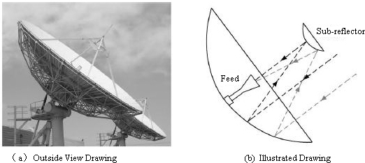
A cassegrain antenna is a parabolic antenna that contains two reflectors. The first, largest reflector is the main dish. Radio waves strike the main dish, and due to the geometry of a parabola, are reflected up to the second reflector. The second reflector is a small convex reflector located some distance from the center of the main dish. When the radio waves strike the second reflector, they are then reflected back down to the receiver [2]. A diagram of cassegrain antenna operation is shown in the figure below.
A cassegrain antenna is a parabolic antenna that contains two reflectors. The first, largest reflector is the main dish. Radio waves strike the main dish, and due to the geometry of a parabola, are reflected up to the second reflector. The second reflector is a small convex reflector located some distance from the center of the main dish. When the radio waves strike the second reflector, they are then reflected back down to the receiver [2]. A diagram of cassegrain antenna operation is shown in the figure below.
Polarization
There are two main types of antenna polarization: linear polarization and circular polarization.
There are two main types of antenna polarization: linear polarization and circular polarization.
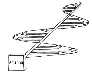
As shown in the images above, an antenna is linearly polarized when its radiation is contained within one plane. A linearly polarized antenna may be either vertically or horizontally polarized. In a vertically polarized antenna, the radiation is perpendicular to the earth. In contrast, a horizontally polarized antenna radiates parallel to the earth.
In a circular polarized antenna, the radiation rotates in a circular motion, radiating energy in all planes. A circular polarized antenna's radiation completes one revolution per wavelength [5].
We chose equipment with circular polarization, because linear polarization has one major disadvantage when it comes to satellite communication. For linear polarization, polarization alignment between sender and receiver is crucial. For example, if linear polarization between sender and receiver is misaligned 90 degrees, the resulting attenuation can be more than 20 dB, greatly reducing signal quality [6]. Circular polarization has no such alignment requirements, making it an ideal choice for satellite communication.
References
[1] - https://www.viasat.com/sites/default/files/legacy/5_meter_fixed_antenna_010_web.pdf
[2} - http://www.gmrt.ncra.tifr.res.in/gmrt_hpage/sub_system/corr/IMH/Documents/Report/CASSEGRAIN.pdf
[3] - http://www.rxantenna.com/
{4] - http://blog.atlasrfidstore.com/circular-polarization-vs-linear-polarization
[5] - http://luxul.com/wp-content/documents/LUX-EB-Use%20of%20CP%20in%20Wi-Fi.pdf
[6] - http://www.air-stream.org.au/technical-references/antenna-polarisation


