Antenna Design
- Gain Pattern
- Center frequency (24.125GHz)
- Bandwidth
- Polarization Circular
- Beam taper
- Sidelobe restriction
(Must also describe Beamwidth (HPBW), Sidelobe level/Front-to-Back Ratio, Radiation Resistance, Max Rated Power, VSWR)
We will utilize a Cassegrain antenna architecture. A Cassegrain antenna must have a minimum diameter of 0.622m (50 wavelengths) with a minimum subreflector diameter of 0.249m (20 wavelengths) before the efficiency is higher than an equivalent dish with a primary feed.[3] Our antenna will transmit circularly polarized (CP) waves. Circular polarization is really two orthogonal linear polarized waves 90 degrees out of phase.[4] The main advantage of CP versus linear polarization is that CP eliminates polarization mismatch losses caused by Faradays rotation and varies the squint angle of polarization vectors between stations on the Earth.[9] With this setup, we should have minimal interruption due to atmospheric effects resulting from our power transmission.
Dish Antenna Trade-off
D1D2=λr
Assuming D2 (in the sky) = 100m, D1 = ((3e8/24.125e9)*20.2e6)/100 = 2.512e3m
r= 20.2e6m (worst case. MEO)
Array Design
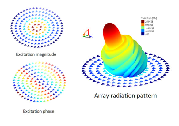
Figure G2.[1] Concentric ring array pattern
To be able to steer the beam, without mechanically steering an antenna that would be around 2.5km in diameter we have decided that the most effective method would be to design an antenna array. We decided to use a uniform circular array instead of a planar array because this would give us the advantage of not having edge elements. Without edge elements, our antenna would be allowed to electronically scan in the azimuthal plane without significant change in beam shape and effectively give us the ability to point our gain pattern in any direction above the horizon.[13]
To steer our beam, we utilize the Minimum Mean Square Error optimal beamforming technique.[13]
Array shape: Circular
Element spacing, d = (1900/2π)*λ = 3.75m
Element excitation amplitude fixed amplitude for steering
Element excitation phase varies on desired direction
Array element pattern
Array Elements
element diameter, D = 300m
dish depth, d = 25m
f focal length = (D2/16d) = 225m,
f/D = 0.75,
# elements in array = 10
Array factor
By the pattern multiplication theorem:
Array pattern = Array element pattern x Array factor(AF)
Array diameter = 2.512e3m
This f/D is acceptable since a smaller f/D is harder to illuminate efficiently and is more sensitive to focal length errors.[3]
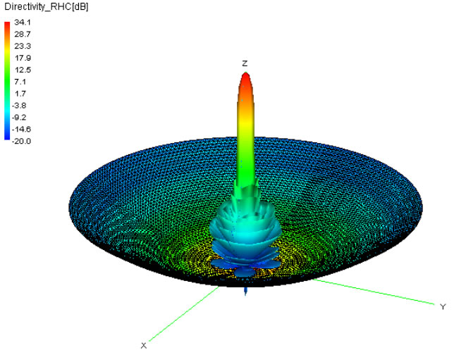
Figure G3.[1] Circularly polarized dish pattern
Beamforming
Optimal Beamforming: MMSE (Minimum Mean Square Error)